Lexus NX: HV Main Relay (P3110-223)
DESCRIPTION
The hybrid vehicle control ECU monitors the IGCT relay and detects the following malfunction.
| DTC No. | Detection Item | DTC Detection Condition | Trouble Area | MIL | Warning Indicate |
|---|---|---|---|---|---|
| P3110-223 | HV Main Relay | IGCT relay stuck on (+B short): IGCT relay is stuck on or a short to B+ exists. Power to the hybrid vehicle control ECU does not shut down when the power switch is turned off. (1 trip detection logic) |
| Does not come on | Master Warning Light: Comes on |
WIRING DIAGRAM
Refer to the wiring diagram for DTC P2511-149.
Click here .gif)
CAUTION / NOTICE / HINT
HINT:
- If auxiliary battery voltage is applied to the +B1 or +B2 terminal in the hybrid vehicle control ECU even when the power switch is turned off, a short to B+ exists.
-
After the repair, clear the DTCs and perform the following procedure to check that DTCs are not output.
- Turn the power switch on (IG) and wait for 15 seconds or more.
- Turn the power switch off and wait for 30 seconds or more.
PROCEDURE
| 1. | INSPECT IGCT RELAY (IGCT) |
(a) Remove the IGCT relay from the No. 1 engine room relay block.
| (b) Measure the resistance according to the value(s) in the table below. Standard Resistance:
|
|
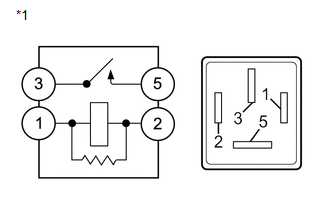
(c) Install the IGCT relay.
| NG | .gif) | REPLACE IGCT RELAY (IGCT) |
|
.gif)
| 2. | CHECK HARNESS AND CONNECTOR (HYBRID VEHICLE CONTROL ECU - NO. 1 ENGINE ROOM RELAY BLOCK) |
(a) Disconnect the A60 and A61 hybrid vehicle control ECU connectors.
(b) Remove the IGCT relay from the No. 1 engine room relay block.
(c) Measure the voltage according to the value(s) in the table below.
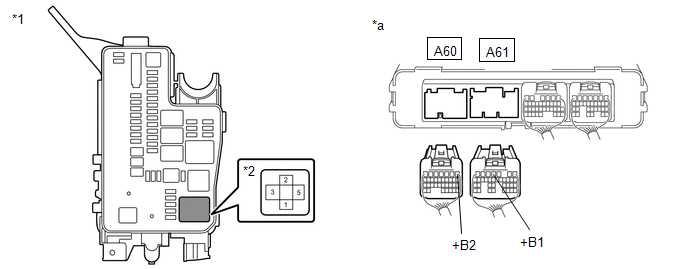
| *1 | No. 1 Engine Room Relay Block | *2 | IGCT Relay |
| *a | Rear view of wire harness connector (to Hybrid Vehicle Control ECU) | - | - |
Standard Voltage:
| Tester Connection | Condition | Specified Condition |
|---|---|---|
| A61-4 (+B1), A60-1 (+B2) or 5 (IGCT relay) - Body ground | Power switch off | Below 1 V |
(d) Install the IGCT relay.
(e) Reconnect the A60 and A61 hybrid vehicle control ECU connectors.
| OK | | REPLACE HYBRID VEHICLE CONTROL ECU |
| NG | | REPAIR OR REPLACE HARNESS OR CONNECTOR |
READ NEXT:
 Transmission system (P3147-239,P3147-241)
DESCRIPTION The hybrid vehicle transaxle assembly consists of the planetary gear unit, generator (MG1) and motor (MG2). The planetary gear unit uses a planetary gear to split the engine output into me
Inverter Coolant Pump Speed Signal (P314A-828)
DESCRIPTION Refer to the description for DTC P0C73-776. Click here The inverter water pump assembly sends the inverter water pump speed (measured value) signal to the hybrid vehicle control ECU. If
All HV Gate Blocking Range/Performance (P321E-318)
DESCRIPTION The hybrid vehicle control ECU sends a block signal to the motor generator control ECU (MG ECU) to shutdown the power supply to the motor. When the system is not in the on (READY) state, i
SEE MORE:
Drive Motor "B" Inverter Performance (P0A79-696)
DTC SUMMARY MALFUNCTION DESCRIPTION This DTC indicates a malfunction inside the inverter for the rear motor. The cause of this malfunction may be one of the following: Area Main Malfunction Description Step Inverter low-voltage circuit The connectors are not connected properly 3 H
Rough Idling (P1605)
DESCRIPTION When the engine is idling stably under a low load, if the idle speed drops or becomes unstable, this DTC will be stored. Read freeze frame data using the Techstream. The ECM records vehicle and driving condition information as freeze frame data the moment a DTC is stored. When troublesho
