Lexus NX: Hybrid Battery Pack Current Sensor Circuit Range / Performance (P0AC0-817)
DESCRIPTION
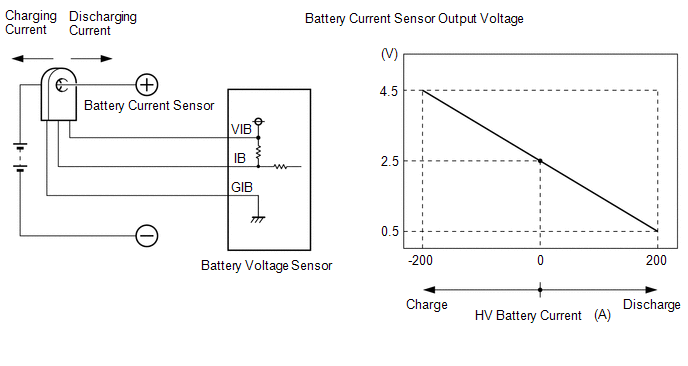
A battery current sensor is installed to the positive (+) cable side of the HV battery and detects current flowing from the HV battery. The battery current sensor outputs voltage, which changes between 0 and 5 V according to the detected amperage, to the IB terminal of the battery voltage sensor. The battery voltage sensor sends signals to the hybrid vehicle control ECU. The hybrid vehicle control ECU determines the charging and discharging amount of the HV battery based on the received signals and calculates the SOC of the HV battery through the accumulated amperage.
| DTC No. | Detection Item | DTC Detection Condition | Trouble Area | MIL | Warning Indicate |
|---|---|---|---|---|---|
| P0AC0-817 | Hybrid Battery Pack Current Sensor Circuit Range / Performance | Abnormal battery current sensor characteristics: An abnormality in the battery current sensor characteristics is detected based on the relationship between hybrid system power consumption and battery power output. (1 trip detection logic) |
| Comes on | Master Warning Light: Comes on |
| DTC No. | Data List |
|---|---|
| P0AC0-817 | - |
MONITOR DESCRIPTION
The hybrid vehicle control ECU detects malfunctions of the battery current sensor by monitoring motor and generator torque. If the hybrid vehicle control ECU detects a battery current sensor malfunction, the hybrid vehicle control ECU will illuminate the MIL and store a DTC.
MONITOR STRATEGY
| Related DTCs | P0AC0 (INF 817): Current sensor malfunction (gain or offset) |
| Required sensors/components | Battery current sensor |
| Frequency of operation | Continuous |
| Duration | TMC's intellectual property |
| MIL operation | 1 driving cycle |
| Sequence of operation | None |
TYPICAL ENABLING CONDITIONS
| The monitor will run whenever the following DTCs are not stored | TMC's intellectual property |
| Other conditions belong to TMC's intellectual property | - |
TYPICAL MALFUNCTION THRESHOLDS
| TMC's intellectual property | - |
COMPONENT OPERATING RANGE
| Hybrid vehicle control ECU | DTC P0AC0 (INF 817) is not detected |
CONFIRMATION DRIVING PATTERN
- Connect the Techstream to the DLC3.
- Turn the power switch on (IG) and turn the Techstream on.
- Clear the DTCs (even if no DTCs are stored, perform the clear DTC procedure).
- Turn the power switch off and wait for 30 seconds or more.
- Turn the power switch on (IG) and turn the Techstream on.
- Turn the power switch on (READY).
- Drive the vehicle for approximately 10 minutes according to the freeze frame data items "Vehicle Spd", "Accelerator Degree", "Power Resource IB", "M(MG2) Trq Exec Val" and "G(MG1) Trq Exec Val".
- Enter the following menus: Powertrain / Hybrid Control / Trouble Codes.
-
Read the current DTCs.
HINT:
- If a current DTC is output, the system is malfunctioning.
- If current DTCs are not output, perform the following steps to check for permanent DTCs.
- Check that the permanent DTCs are cleared.
- If the permanent DTCs are not cleared, perform the universal trip, and then check for permanent DTCs again.
CAUTION / NOTICE / HINT
HINT:
After the repair, clear the DTCs and perform the following procedure to check that DTCs are not output.
- Drive the vehicle for approximately 10 minutes according to the freeze frame data items "Vehicle Spd", "Accelerator Degree", "Power Resource IB", "M(MG2) Trq Exec Val" and "G(MG1) Trq Exec Val".
PROCEDURE
| 1. | CHECK DTC OUTPUT (HYBRID CONTROL) |
(a) Connect the Techstream to the DLC3.
(b) Turn the power switch on (IG).
(c) Enter the following menus: Powertrain / Hybrid Control / Trouble Codes.
(d) Check for DTCs.
Powertrain > Hybrid Control > Trouble Codes| Result | Proceed to |
|---|---|
| P0AC0-817 only is output. | A |
| P0AFC-123 is output. | B |
(e) Turn the power switch off.
| B | .gif) | GO TO DTC CHART (P0AFC-123) |
|
.gif)
| 2. | REPLACE HV BATTERY JUNCTION BLOCK ASSEMBLY |
Click here .gif)
|
| 3. | CLEAR DTC |
Click here
|
| 4. | PERFORM ROAD TEST |
(a) Drive the vehicle for approximately 10 minutes according to the freeze frame data items "Vehicle Spd", "Accelerator Degree", "Power Resource IB", "M(MG2) Trq Exec Val" and "G(MG1) Trq Exec Val".
CAUTION:
When performing the confirmation driving pattern, obey all speed limits and traffic laws.
|
| 5. | CHECK DTC OUTPUT (HYBRID CONTROL) |
(a) Connect the Techstream to the DLC3.
(b) Turn the power switch on (IG).
(c) Enter the following menus: Powertrain / Hybrid Control / Trouble Codes.
(d) Check for DTCs.
Powertrain > Hybrid Control > Trouble Codes(e) Turn the power switch off.
| P0AC0-817 is not output. | | COMPLETED |
| P0AC0-817 is output again. | | REPLACE BATTERY VOLTAGE SENSOR |
READ NEXT:
 Hybrid Battery Positive Contactor Control Circuit Low (P0ADB-227)
DESCRIPTION Refer to the description for DTC P0AE6-225. Click here DTC No. Detection Item DTC Detection Condition Trouble Area MIL Warning Indicate P0ADB-227 Hybrid Battery Positi
Hybrid Battery Precharge Contactor Circuit Stuck Closed (P0AE2-773)
DTC SUMMARY MALFUNCTION DESCRIPTION The hybrid vehicle control ECU detects a stuck closed malfunction of a precharge relay stuck malfunction on the HV battery negative side. The cause of this malfunct
Drive Motor Inverter Temperature Sensor "A" Circuit Low (P0AEF-275,P0AF0-274)
DESCRIPTION The MG ECU, which is built into in the inverter with converter assembly, detects the temperature of the motor inverter using a temperature sensor built into the inverter with converter ass
SEE MORE:
Interior Light Auto Cut Circuit
DESCRIPTION The main body ECU (multiplex network body ECU) controls the DOME CUT relay. WIRING DIAGRAM CAUTION / NOTICE / HINT NOTICE:
Inspect the fuses for circuits related to this system before performing the following procedure.
Recognition code registration is necessary when replacing the
On-vehicle Inspection
ON-VEHICLE INSPECTION PROCEDURE 1. INSPECT AIR CONDITIONER PRESSURE SENSOR (a) Check the wire harness. *a Component without harness connected (Air Conditioner Pressure Sensor) *b Component without harness connected (Air Conditioning Amplifier Assembly) (1) Disconnect the A18 air condi
