Lexus NX: Components
COMPONENTS
ILLUSTRATION
.png)
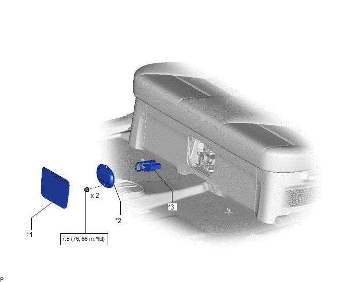
| *1 | DECK FLOOR BOX LH | *2 | NO. 3 DECK BOARD SUB-ASSEMBLY |
| *3 | REAR DECK FLOOR BOX | *4 | NEGATIVE AUXILIARY BATTERY TERMINAL |
.png) | N*m (kgf*cm, ft.*lbf): Specified torque | - | - |
ILLUSTRATION
| *1 | BATTERY SERVICE HOLE COVER | *2 | HYBRID BATTERY SERVICE PLUG COVER |
| *3 | SERVICE PLUG GRIP | - | - |
| | N*m (kgf*cm, ft.*lbf): Specified torque | - | - |
ILLUSTRATION
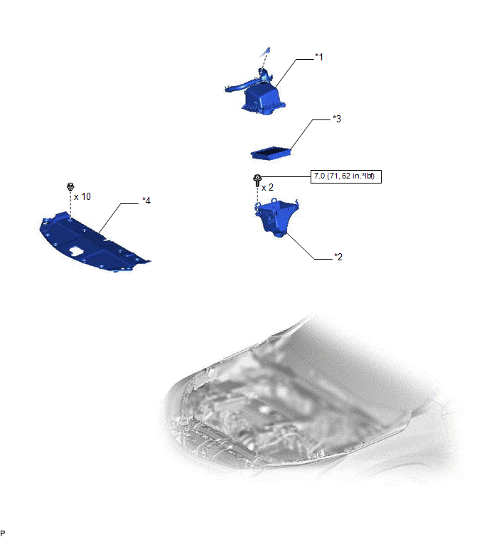
| *1 | AIR CLEANER CAP SUB-ASSEMBLY | *2 | AIR CLEANER CASE SUB-ASSEMBLY |
| *3 | AIR CLEANER FILTER ELEMENT SUB-ASSEMBLY | *4 | RADIATOR SUPPORT OPENING COVER |
| | N*m (kgf*cm, ft.*lbf): Specified torque | - | - |
ILLUSTRATION
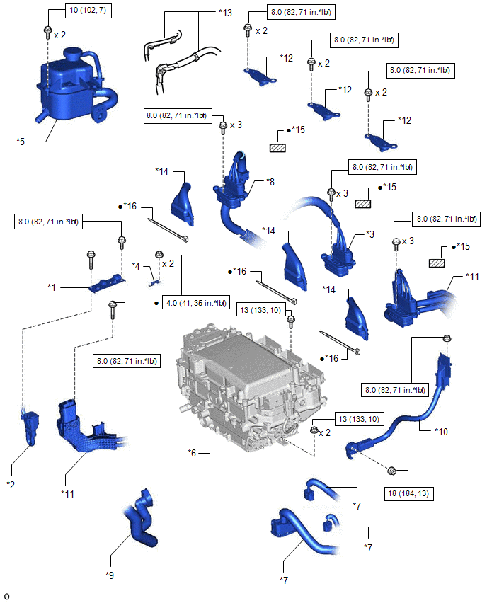
| *1 | CONNECTOR COVER ASSEMBLY | *2 | ENGINE WIRE |
| *3 | GENERATOR CABLE | *4 | HIGH VOLTAGE FUSE |
| *5 | INVERTER RESERVE TANK ASSEMBLY | *6 | INVERTER WITH CONVERTER ASSEMBLY |
| *7 | LOW VOLTAGE CONNECTOR | *8 | MOTOR CABLE |
| *9 | NO. 2 INVERTER COOLING HOSE ASSEMBLY | *10 | NO. 3 ENGINE ROOM WIRE |
| *11 | NO. 2 FRAME WIRE | *12 | UPPER INVERTER COVER |
| *13 | WIRE HARNESS | *14 | WIRE HARNESS BOOT |
| *15 | INSULATING TAPE | *16 | TIE BAND |
| | N*m (kgf*cm, ft.*lbf): Specified torque | ● | Non-reusable part |
ILLUSTRATION
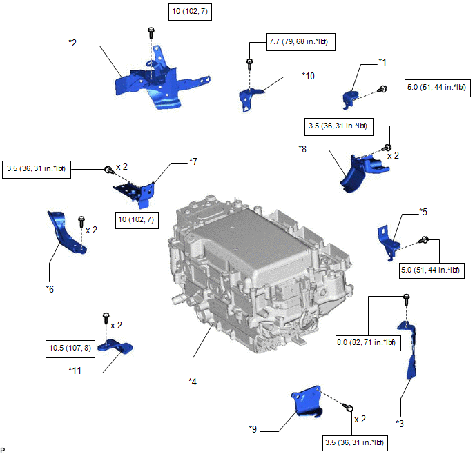
| *1 | AIR CLEANER BRACKET | *2 | HYBRID INVERTER PROTECTOR ASSEMBLY |
| *3 | INVERTER PROTECTOR | *4 | INVERTER WITH CONVERTER ASSEMBLY |
| *5 | NO. 1 AIR CLEANER BRACKET | *6 | NO. 2 INVERTER RESERVE TANK BRACKET |
| *7 | NO. 2 INVERTER BRACKET | *8 | NO. 3 INVERTER BRACKET |
| *9 | NO. 4 INVERTER BRACKET | *10 | WIRE HARNESS CLAMP BRACKET |
| *11 | NO. 6 INVERTER BRACKET | - | - |
| | N*m (kgf*cm, ft.*lbf): Specified torque | - | - |
READ NEXT:
 Removal
REMOVAL PROCEDURE 1. PRECAUTION Click here 2. REMOVE SERVICE PLUG GRIP Click here 3. DRAIN COOLANT (for Inverter Coolant) Click here 4. DISCONNECT WIRE HARNESS (a) Disconnect the 4 wire harn
Installation
INSTALLATION CAUTION / NOTICE / HINT NOTICE:
When replacing with a new inverter with converter assembly, securely lock the retainer of the inverter cooling hose since it is not locked.
Before rep
Relay
On-vehicle InspectionON-VEHICLE INSPECTION PROCEDURE 1. INSPECT IGNITION CONTROL RELAY (IGCT) (a) Measure the resistance according to the value(s) in the table below. Standard Resistance: Test
SEE MORE:
Installation
INSTALLATION PROCEDURE 1. INSTALL INTEGRATION CONTROL AND PANEL ASSEMBLY (BRAKE HOLD SWITCH) (a) Install the integration control and panel assembly (brake hold switch) to the upper rear console panel sub-assembly with the 2 screws. HINT: The locations labeled A in the illustration are tightened t
Hood Support
ComponentsCOMPONENTS ILLUSTRATION *1 HOOD STAY BRACKET LH *2 HOOD SUPPORT ASSEMBLY *3 STOP RING - - N*m (kgf*cm, ft.*lbf): Specified torque - - RemovalREMOVAL CAUTION / NOTICE / HINT HINT:
Use the same procedure for both the RH and LH side.
The procedure desc
