
Lexus NX: Inspection
INSPECTION
PROCEDURE
1. INSPECT FUEL LID WITH MOTOR LOCK ASSEMBLY
| (a) Check the operation of the fuel lid with lock motor assembly. (1) Apply auxiliary battery voltage to the fuel lid with motor lock assembly connector, and check that the fuel lid with motor lock assembly operates smoothly as follows. Standard:
If the result is not as specified, replace the fuel lid with motor lock assembly. |
|
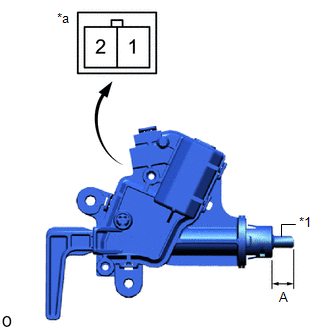
(b) Measure the shaft stroke.
Standard:
| Area | Lock Condition | Specified Condition |
|---|---|---|
| A | Unlock | 0 mm (0 in.) |
| Lock | 11.0 +/- 0.7 mm (0.4331 +/- 0.0276 in.) |
READ NEXT:
 Installation
INSTALLATION PROCEDURE 1. INSTALL FUEL LID WITH MOTOR LOCK ASSEMBLY (a) Connect the connector. (b) Install the fuel lid with motor lock assembly. 2. INSTALL FUEL FILLER OPENING LID LOCK RETAINER (a
Parts Location
PARTS LOCATION ILLUSTRATION *A w/ Power Back Door System *B w/o Power Back Door System *1 DOOR CONTROL SWITCH *2 MULTIPLEX NETWORK MASTER SWITCH ASSEMBLY *3 FRONT DOOR LOCK A
SEE MORE:
Removal
REMOVAL PROCEDURE 1. FRONT WHEELS FACING STRAIGHT AHEAD 2. SECURE STEERING WHEEL Click here 3. REMOVE COLUMN HOLE COVER SILENCER SHEET Click here 4. DISCONNECT NO. 2 STEERING INTERMEDIATE SHAFT ASSEMBLY Click here 5. REMOVE FRONT WHEELS Click here 6. REMOVE NO. 1 ENGINE UNDER COVER ASSEMBLY
Adjustment
ADJUSTMENT CAUTION / NOTICE / HINT HINT:
Use the same procedure for the RH and LH sides.
The procedure listed below is for the LH side.
It is possible that a fog light assembly is incorrectly installed, affecting fog light aim. Fog light assembly installation should be considered prior to per
