Lexus NX: Inspection
INSPECTION
PROCEDURE
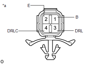
1. INSPECT CLEARANCE LIGHT ASSEMBLY LH
| (a) Apply battery voltage to the connector and check the light illumination condition. OK:
If the result is not as specified, replace the clearance light assembly LH. |
|
2. INSPECT CLEARANCE LIGHT ASSEMBLY RH
| (a) Apply battery voltage to the connector and check the light illumination condition. OK:
If the result is not as specified, replace the clearance light assembly RH. |
|

READ NEXT:
 Installation
INSTALLATION CAUTION / NOTICE / HINT HINT:
Use the same procedure for the RH and LH sides.
The procedure described below is for the LH side.
PROCEDURE 1. INSTALL CLEARANCE LIGHT ASSEMBLY LH (a
Components
COMPONENTS ILLUSTRATION *1 FOG LIGHT ASSEMBLY LH *2 FRONT BUMPER ASSEMBLY
SEE MORE:
Egr Cooler
ComponentsCOMPONENTS ILLUSTRATION *1 EGR COOLER ASSEMBLY *2 NO. 5 WATER BY-PASS HOSE *3 STUD BOLT *4 GASKET *5 NO. 1 WATER BY-PASS PIPE *6 NO. 1 EGR PIPE N*m (kgf*cm, ft.*lbf): Specified torque ● Non-reusable part RemovalREMOVAL PROCEDURE 1. REMOVE EXH
Windshield Deicer does not Operate
DESCRIPTION When the windshield deicer switch is operated, the operation signal is transmitted to the radio receiver assembly. The radio receiver assembly transmits the operation signal to the air conditioning amplifier assembly via the CAN communication line. WIRING DIAGRAM CAUTION / NOTICE / HINT
