
Lexus NX: Reassembly
Lexus NX Service Manual / Vehicle Exterior / Lighting (ext) / Rear Combination Light Assembly / Reassembly
REASSEMBLY
CAUTION / NOTICE / HINT
HINT:
- Use the same procedure for the RH and LH sides.
- The procedure listed below is for the LH side.
PROCEDURE
1. INSTALL REAR COMBINATION LIGHT SOCKET AND WIRE SUB-ASSEMBLY LH
NOTICE:
- Prevention of static electricity is required during this procedure.
- Use static electricity countermeasures SST (desktop anti-static mat set) and observe all precautions to prevent damage to the system by electrostatic discharge (ESD).
- Perform work using clean rubber gloves.
- Do not touch the rear combination light socket and wire sub-assembly LH connector with bare hands.
SST: 09890-47010
09891-04010
09891-04020
09891-04030
09891-04040
(a) Attach the 2 wire harness clamps to install the rear combination light socket and wire sub-assembly LH.
(b) Connect the connector.
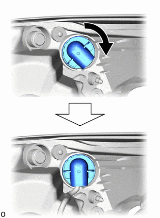
| (c) Rotate the connector cap clockwise until it stops to connect the connector cap. |
|
2. INSTALL REAR COMBINATION LIGHT RETAINER LH
| (a) Attach the 2 guides to Install the rear combination light retainer LH. |
|
.png)
(b) Attach the wire harness clamp.
READ NEXT:
 Installation
INSTALLATION CAUTION / NOTICE / HINT HINT:
Use the same procedure for the RH and LH sides.
The procedure described below is for the LH side.
PROCEDURE 1. INSTALL REAR COMBINATION LIGHT ASSEMBL
Components
COMPONENTS ILLUSTRATION *A w/o Power Back Door System *B w/ Power Back Door System *1 BACK DOOR FINISH COVER LH *2 BACK DOOR FINISH COVER RH *3 BACK DOOR LOCK COVER *4 BA
SEE MORE:
Dtc Check / Clear
DTC CHECK / CLEAR CHECK DTC (CHECK USING Techstream) (a) Connect the Techstream to the DLC3. (b) Turn the power switch on (IG) and wait for 90 seconds. (c) Turn the Techstream on. (d) Enter the following menus: Body Electrical / Navigation System / Trouble Codes. Body Electrical > Navigation Syst
Components
COMPONENTS ILLUSTRATION *1 TAIL EXHAUST PIPE ASSEMBLY *2 EXHAUST PIPE SUPPORT *3 COMPRESSION SPRING - - N*m (kgf*cm, ft.*lbf): Specified torque - - ILLUSTRATION *1 REAR AXLE SHAFT NUT LH *2 REAR DRIVE SHAFT ASSEMBLY LH *3 REAR SUSPENSION ARM COVER LH
© 2016-2026 Copyright www.lexunx.com
