Lexus NX: Installation
INSTALLATION
CAUTION / NOTICE / HINT
HINT:
- Use the same procedure for the RH and LH sides.
- The procedure described below is for the LH side.
PROCEDURE
1. INSTALL SIDE TURN SIGNAL LIGHT ASSEMBLY LH
(a) Connect the connector.
(b) Align the side turn signal light assembly LH with the alignment point on the outer mirror assembly LH and set it in place.
.png) | Alignment Point |
(c) Attach the 2 claws to install the side turn signal light assembly LH.
2. INSTALL LOWER OUTER MIRROR COVER LH
(a) Attach the 2 guides and 3 claws to install the lower outer mirror cover LH.
(b) Install the screw.
(c) w/ Panoramic View Monitor System:
Attach the wire harness clamp and connect the connector.
3. INSTALL OUTER MIRROR BEZEL LH
(a) Attach the guide and 5 claws to install the outer mirror bezel LH.
4. INSTALL OUTER MIRROR COVER LH
(a) Attach the 2 guides and 6 claws to install the outer mirror cover LH.
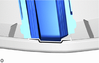
5. INSTALL OUTER MIRROR LH
Click here .gif)
6. INSPECT SIDE TURN SIGNAL LIGHT
(a) Turn the power switch on (IG).
(b) Turn the side turn signal switch left to right and check that the side turn signal light illuminates.
READ NEXT:
 Components
COMPONENTS ILLUSTRATION *1 COWL SIDE TRIM BOARD LH *2 DOOR SCUFF PLATE ASSEMBLY LH *3 INSTRUMENT SIDE PANEL LH *4 LOWER NO. 1 INSTRUMENT PANEL FINISH PANEL *5 NO. 1 INSTRUMEN
On-vehicle Inspection
ON-VEHICLE INSPECTION PROCEDURE 1. INSPECT STOP LIGHT CONTROL ECU ASSEMBLY (a) Disconnect the stop light control ECU assembly connector. *a Front view of wire harness connector (to S
SEE MORE:
Open in One Side of Bus 5 Branch Line
DESCRIPTION When the CAN bus main lines are normal (no open, short to ground, short to +B or short between lines) and there is an ECU or sensor on the "Communication Bus Check" screen that is indicated as not communicating or whose connection status on the "Communication Bus Check" screen changes in
Terminals Of Ecu
TERMINALS OF ECU CHECK INSTRUMENT PANEL JUNCTION BLOCK ASSEMBLY, MAIN BODY ECU (MULTIPLEX NETWORK BODY ECU) (a) Remove the main body ECU (multiplex network body ECU) from the instrument panel junction block assembly. Click here *1 Main Body ECU (Multiplex Network Body ECU) - - (b) Co
