
Lexus NX: Inspection
INSPECTION
CAUTION / NOTICE / HINT
CAUTION:
Make sure that fingers or articles of clothing do not get caught in moving parts when performing this test.
PROCEDURE
1. INSPECT WINDSHIELD WIPER MOTOR ASSEMBLY
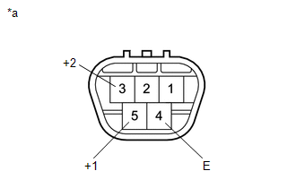
| *a | Component without harness connected (Windshield Wiper Motor Assembly) |
(a) Check the LO operation.
(1) Apply auxiliary battery voltage to the windshield wiper motor connector and check the speed of the windshield wiper motor assembly.
OK:
| Measurement Condition | Specified Condition |
|---|---|
| Auxiliary battery positive (+) → Terminal 5 (+1) Auxiliary battery negative (-) → Terminal 4 (E) | Motor operates at low speed |
(b) Check the HI operation.
(1) Apply auxiliary battery voltage to the windshield wiper motor connector and check the speed of the windshield wiper motor assembly.
OK:
| Measurement Condition | Specified Condition |
|---|---|
| Auxiliary battery positive (+) → Terminal 3 (+2) Auxiliary battery negative (-) → Terminal 4 (E) | Motor operates at high speed |
If the result is not as specified, replace the windshield wiper motor assembly.
READ NEXT:
 Removal
REMOVAL PROCEDURE 1. REMOVE FRONT WIPER ARM HEAD CAP (a) Using a screwdriver, detach the 3 claws and remove the front wiper arm head cap. HINT:
Tape the screwdriver tip before use.
Use the sam
Installation
INSTALLATION PROCEDURE 1. INSTALL WINDSHIELD WIPER MOTOR ASSEMBLY (a) Install the windshield wiper motor assembly to the windshield wiper link assembly with the 3 bolts. Torque: 5.4 N·m {55 kgf·cm,
Front Wiper Rubber
ComponentsCOMPONENTS ILLUSTRATION *1 FRONT WIPER BLADE LH *2 WIPER RUBBER LH ReplacementREPLACEMENT CAUTION / NOTICE / HINT HINT:
Use the same procedure for RHD and LHD vehicles.
SEE MORE:
Child safety
Riding with children
Observe the following precautions
when children are in the vehicle.
Use a child restraint system appropriate
for the child, until the child
becomes large enough to properly
wear the vehicle's seat belt.
It is recommended that children
sit in the rear seats to avoid
No. 1 Clearance Warning Buzzer Circuit
DESCRIPTION This circuit consists of the No. 1 clearance warning buzzer and clearance warning ECU assembly. An ECU-excited type buzzer is used. The ECU operates the buzzers using a sound pattern that changes depending on the distance to the obstacle. WIRING DIAGRAM PROCEDURE 1. PERFORM ACTIVE
