Lexus NX: Installation
INSTALLATION
PROCEDURE
1. INSTALL WINDSHIELD WIPER MOTOR ASSEMBLY
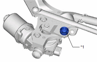
(a) Install the windshield wiper motor assembly to the windshield wiper link assembly with the 3 bolts.
Torque:
5.4 N·m {55 kgf·cm, 48 in·lbf}
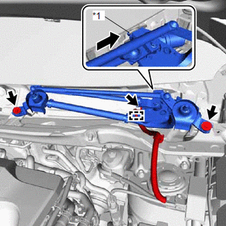
(b) Attach the motor grommet to temporarily install the windshield wiper motor and link assembly with the 2 bolts.
(c) Connect the windshield wiper motor assembly connector.
(d) Turn the power switch on (IG).
(e) Operate the wiper switch and stop the windshield wiper motor assembly at the automatic stop (park) position.
(f) Turn the power switch off.
(g) Disconnect the windshield wiper motor assembly connector.
(h) Remove the 2 bolts.
(i) Detach the motor grommet as shown in the illustration and remove the windshield wiper motor and link assembly.
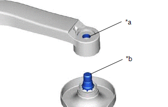
(j) Temporarily install the windshield wiper motor crank to the windshield wiper motor assembly with the nut.
(k) Temporarily place the No. 1 windshield wiper link rod in the windshield wiper motor crank pivot.
(l) Align the windshield wiper motor assembly shaft and crank arm pivot with the No. 1 windshield wiper link rod in a straight line as shown in the illustration.
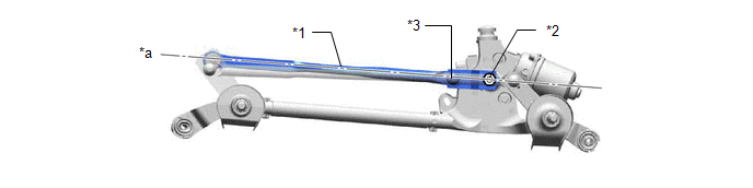
| *1 | No. 1 Windshield Wiper Link Rod | *2 | Windshield Wiper Motor Assembly Shaft |
| *3 | Windshield Wiper Motor Crank Pivot | - | - |
| *a | Straight Line | - | - |
| (m) Using a screwdriver, hold the windshield wiper motor crank as shown in the illustration. HINT: Tape the screwdriver tip before use. |
|
.png)
(n) Tighten the nut.
Torque:
8.5 N·m {87 kgf·cm, 75 in·lbf}
| (o) Apply MP grease to the windshield wiper motor crank pivot. |
|
(p) Connect the No. 1 windshield wiper link rod to the windshield wiper motor crank pivot.
2. INSTALL WINDSHIELD WIPER MOTOR AND LINK ASSEMBLY
NOTICE:
Be careful not to damage the windshield when installing the windshield wiper motor and link assembly.
(a) Connect the connector.
(b) Attach the clamp
| (c) Attach the motor grommet to temporarily install the windshield wiper motor and link assembly as shown in the illustration. |
|
(d) Install the windshield wiper motor and link assembly with the 2 bolts.
Torque:
5.5 N·m {56 kgf·cm, 49 in·lbf}
3. INSTALL COWL TOP VENTILATOR LOUVER SUB-ASSEMBLY
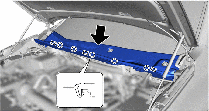
(a) Push the cowl top ventilator louver in the direction indicated by the arrow in the illustration to attach the 9 guides.
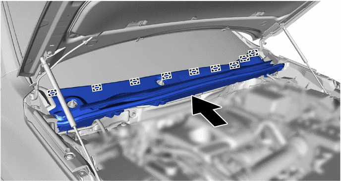
(b) Attach the 5 claws and 3 guides and install the cowl top ventilator louver in the direction indicated by the arrow in the illustration.
(c) Install the 2 clips.
(d) Attach the 2 claws of the front fender to cowl side seal RH.
(e) Attach the 2 claws of the front fender to cowl side seal LH.
4. INSTALL WINDSHIELD WIPER ARM AND BLADE ASSEMBLY RH
(a) When reinstalling:
| (1) Clean the wiper arm serrations. NOTICE: Do not grind the serrations excessively. |
|
(b) Clean the wiper pivot serrations.
NOTICE:
Do not grind the serrations excessively.
(c) Turn the power switch on (IG).
(d) Operate the wiper switch and stop the windshield wiper motor assembly at the automatic stop (park) position.
(e) Turn the power switch off.
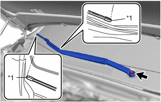
| (f) Align the windshield wiper arm and blade assembly RH as shown in the illustration and install it with the nut. Torque: 26 N·m {265 kgf·cm, 19 ft·lbf} HINT: Hold the arm hinge by hand when tightening the nut. |
|
5. INSTALL WINDSHIELD WIPER ARM AND BLADE ASSEMBLY LH
(a) When reinstalling:
| (1) Clean the wiper arm serrations. NOTICE: Do not grind the serrations excessively. |
|
(b) Clean the wiper pivot serrations.
NOTICE:
Do not grind the serrations excessively.
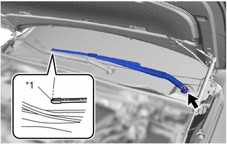
| (c) Align the windshield wiper arm and blade assembly LH as shown in the illustration and install it with the nut. Torque: 26 N·m {265 kgf·cm, 19 ft·lbf} HINT: Hold the arm hinge by hand when tightening the nut. |
|
(d) Operate the front wipers while spraying washer fluid on the glass. Make sure that the front wipers function properly and the wipers do not come into contact with the vehicle body.
(e) Raise the wiper arm 2 times and check that the tip of the front wiper blade is at the position shown in the illustration.
HINT:
Use the same procedure for the RH side.
6. INSTALL FRONT WIPER ARM HEAD CAP
(a) Attach the 3 claws to install the front wiper arm head cap.
HINT:
Use the same procedure for both front wiper arm head caps.
READ NEXT:
 Front Wiper Rubber
ComponentsCOMPONENTS ILLUSTRATION *1 FRONT WIPER BLADE LH *2 WIPER RUBBER LH ReplacementREPLACEMENT CAUTION / NOTICE / HINT HINT:
Use the same procedure for RHD and LHD vehicles.
Headlight Cleaner Actuator
ComponentsCOMPONENTS ILLUSTRATION *1 HEADLIGHT CLEANER WASHER BRACKET *2 HEADLIGHT WASHER ACTUATOR SUB-ASSEMBLY LH *3 HEADLIGHT WASHER ACTUATOR SUB-ASSEMBLY RH *4 NO. 2 HEADLIGHT
Headlight Cleaner Actuator Cover
ComponentsCOMPONENTS ILLUSTRATION *1 HEADLIGHT CLEANER WASHER NOZZLE COVER LH *2 HEADLIGHT CLEANER WASHER NOZZLE COVER RH *3 HEADLIGHT WASHER ACTUATOR SUB-ASSEMBLY LH *4 HEADLIGHT
SEE MORE:
CD/DVD Sound Skips
CAUTION / NOTICE / HINT NOTICE: When replacing the radio receiver assembly, always replace it with a new one. If a radio receiver assembly which was installed to another vehicle is used, the following may occur:
A communication malfunction DTC may be stored.
The radio receiver assembly may not
Parts Location
PARTS LOCATION ILLUSTRATION *1 ENGINE ROOM RELAY BLOCK
- AM2 FUSE
*2 WIRELESS DOOR LOCK BUZZER *3 DOOR CONTROL RECEIVER - - ILLUSTRATION *A w/o Power Back Door System *B w/ Power Back Door System *1 BACK DOOR COURTESY LIGHT SWITCH ASSEMBLY *2 BACK DOO
