Lexus NX: Inspection
INSPECTION
PROCEDURE
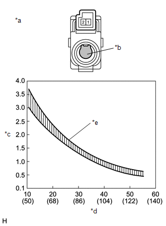
1. INSPECT COOLER THERMISTOR (ROOM TEMPERATURE SENSOR)
| (a) Measure the resistance according to the value(s) in the table below. Standard Resistance:
NOTICE:
HINT: As the temperature increases, the resistance decreases (see the graph).
|
|
READ NEXT:
 Installation
INSTALLATION CAUTION / NOTICE / HINT HINT:
Use the same procedure for RHD and LHD vehicles.
The procedure listed below is for LHD vehicles.
PROCEDURE 1. INSTALL COOLER THERMISTOR (ROOM TEMPERA
Solar Sensor
ComponentsCOMPONENTS ILLUSTRATION *1 AUTOMATIC LIGHT CONTROL SENSOR (SOLAR SENSOR) *2 NO. 1 SPEAKER OPENING COVER ASSEMBLY RemovalREMOVAL PROCEDURE 1. REMOVE NO. 1 SPEAKER OPENING COVER
SEE MORE:
Removal
REMOVAL PROCEDURE 1. REMOVE HORN BUTTON ASSEMBLY Click here 2. REMOVE CRUISE CONTROL MAIN SWITCH (a) Remove the 2 screws. *a Guide (b) Detach the guide. (c) Disconnect the connector and remove the cruise control main switch.
Data List / Active Test
DATA LIST / ACTIVE TEST DATA LIST NOTICE: In the table below, the values listed under "Normal Condition" are reference values. Do not depend solely on these reference values when deciding whether a part is faulty or not. HINT: Using the Techstream to read the Data List allows the values or states of
