Lexus NX: Solar Sensor
Components
COMPONENTS
ILLUSTRATION
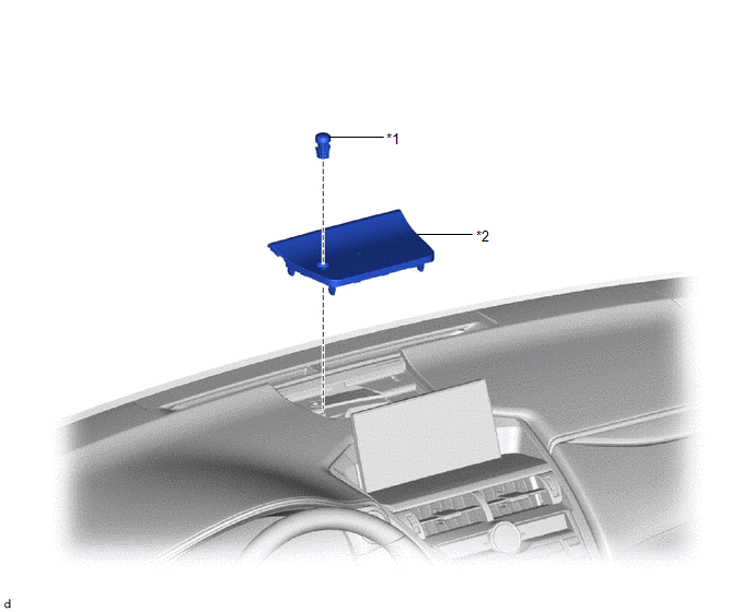
| *1 | AUTOMATIC LIGHT CONTROL SENSOR (SOLAR SENSOR) | *2 | NO. 1 SPEAKER OPENING COVER ASSEMBLY |
Removal
REMOVAL
PROCEDURE
1. REMOVE NO. 1 SPEAKER OPENING COVER ASSEMBLY
Click here .gif)
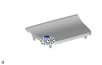
2. REMOVE AUTOMATIC LIGHT CONTROL SENSOR (SOLAR SENSOR)
| (a) Detach the 2 claws and remove the automatic light control sensor (solar sensor). |
|
Inspection
INSPECTION
PROCEDURE
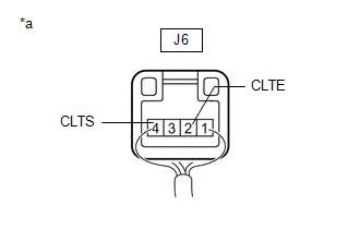
1. INSPECT AUTOMATIC LIGHT CONTROL SENSOR (SOLAR SENSOR)
| (a) Disconnect the J6 automatic light control sensor connector. |
|
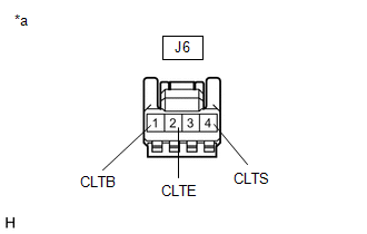
(b) Measure the voltage and resistance according to the value(s) in the table below.
Standard Voltage:
| Tester Connection | Condition | Specified Condition |
|---|---|---|
| J6-1 (CLTB) - J6-2 (CLTE) | Power switch off, dimmer switch off, 2 minutes after all doors closed | Below 1 V |
| Power switch on (IG) | 11 to 14 V |
Standard Resistance:
| Tester Connection | Condition | Specified Condition |
|---|---|---|
| J6-2 (CLTE) - Body ground | Always | Below 1 Ω |
If the result is not as specified, there may be a malfunction on the wire harness side.
| (c) Reconnect the J6 automatic light control sensor connector. |
|
(d) Connect an oscilloscope to the automatic light control sensor connector.
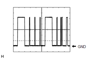
| (e) Check the waveform. OK:
HINT: The communication waveform changes according to the surrounding brightness. If the result is not as specified, the automatic light control sensor may be malfunctioning. |
|
Installation
INSTALLATION
PROCEDURE
1. INSTALL AUTOMATIC LIGHT CONTROL SENSOR (SOLAR SENSOR)
(a) Attach the 2 claws to install the automatic light control sensor (solar sensor).
2. INSTALL NO. 1 SPEAKER OPENING COVER ASSEMBLY
Click here .gif)
READ NEXT:
 Components
COMPONENTS ILLUSTRATION *1 COMBINATION SWITCH ASSEMBLY *2 CONSOLE ARMREST ASSEMBLY *3 INSTRUMENT SIDE PANEL LH *4 LOWER NO. 1 INSTRUMENT PANEL FINISH PANEL *5 NO. 1 INSTRUMEN
SEE MORE:
Components
COMPONENTS ILLUSTRATION *A w/ Woofer *B w/o Woofer *1 BACK DOOR CENTER GARNISH *2 BACK DOOR LOCK COVER *3 BACK DOOR SIDE GARNISH LH *4 BACK DOOR SIDE GARNISH RH *5 BACK DOOR TRIM BASE *6 BACK DOOR TRIM BOARD ASSEMBLY *7 POWER BACK DOOR WARNING BUZZER *
Components
COMPONENTS ILLUSTRATION *1 DECK FLOOR BOX LH *2 NO. 3 DECK BOARD SUB-ASSEMBLY *3 REAR DECK FLOOR BOX *4 AUXILIARY BATTERY NEGATIVE TERMINAL N*m (kgf*cm, ft.*lbf): Specified torque - - ILLUSTRATION *1 COWL SIDE TRIM BOARD LH *2 DOOR SCUFF PLATE ASSEMBLY LH
