Lexus NX: Inspection
INSPECTION
PROCEDURE
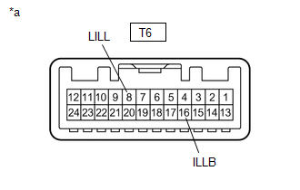
1. INSPECT MAP LIGHT ASSEMBLY (PERSONAL LIGHT)
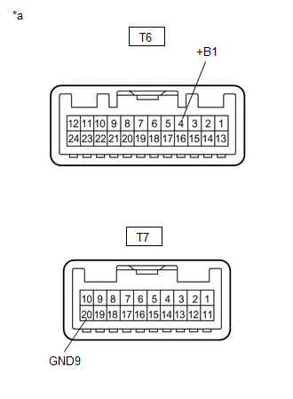
| (a) Inspect the front map light. (1) Apply battery voltage to the connector and check the light illumination condition. OK:
If the result is not as specified, replace the map light assembly (personal light). |
|
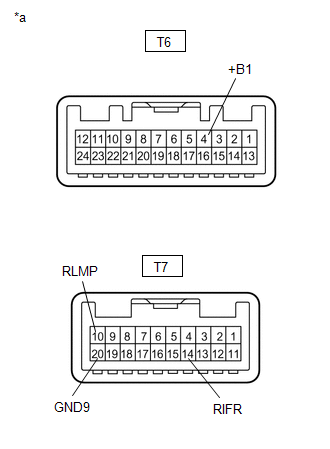
| (b) Inspect the front dome light. (1) Apply battery voltage to the connector and check the light illumination condition. OK:
If the result is not as specified, replace the map light assembly (personal light). |
|
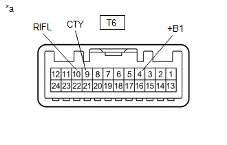
| (c) Inspect internal circuit. (1) Measure the resistance according to the value(s) in the table below. Standard Resistance:
If the result is not as specified, replace the map light assembly (personal light). |
|
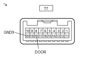
| (d) Inspect the door switch. (1) Measure the resistance according to the value(s) in the table below. Standard Resistance:
If the result is not as specified, replace the map light assembly (personal light). |
|
| (e) Inspect the switch illumination. (1) Apply battery voltage to the connector and check the light illumination condition. OK:
If the result is not as specified, replace the map light assembly (personal light). |
|
READ NEXT:
 Reassembly
REASSEMBLY PROCEDURE 1. INSTALL MAP LIGHT SUB-ASSEMBLY (a) Attach the 17 claws to install the map light sub-assembly.
Installation
INSTALLATION PROCEDURE 1. INSTALL MAP LIGHT ASSEMBLY (PERSONAL LIGHT) (a) Connect the connectors. (b) Attach the 4 clips to install the map light assembly (personal light).
Rear Door Courtesy Switch
ComponentsCOMPONENTS ILLUSTRATION *1 REAR DOOR COURTESY LIGHT SWITCH ASSEMBLY - - N*m (kgf*cm, ft.*lbf): Specified torque - - RemovalREMOVAL CAUTION / NOTICE / HINT HINT:
SEE MORE:
Drive Motor Inverter Temperature Sensor "A" Circuit Low (P0AEF-275,P0AF0-274)
DESCRIPTION The MG ECU, which is built into in the inverter with converter assembly, detects the temperature of the motor inverter using a temperature sensor built into the inverter with converter assembly. The inverter cooling system operates independently of the engine cooling system. The MG ECU u
Diagnosis System
DIAGNOSIS SYSTEM CHECK DLC3 (a) Check the DLC3. Click here INSPECT AUXILIARY BATTERY VOLTAGE (a) Check the auxiliary battery voltage. Standard voltage: 11 to 14 V (power switch off) If the voltage is below 11 V, recharge or replace the auxiliary battery.
