Lexus NX: Inspection
INSPECTION
PROCEDURE
1. INSPECT TRIP SWITCH (LIGHT CONTROL RHEOSTAT)
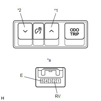
| *1 | Up Switch |
| *2 | Down Switch |
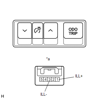
| *a | Component without harness connected (Trip Switch (Light Control Rheostat)) |
(a) Check the resistance.
Measure the resistance according to the value(s) in the table below.
Standard Resistance:
| Tester Connection | Switch Condition | Specified Condition |
|---|---|---|
| 2 (RV) - 5 (E) | Up switch on (Pushed) | Below 1 Ω |
| Up switch off (Not pushed) | 10 kΩ or higher | |
| 2 (RV) - 5 (E) | Down switch on (Pushed) | 1.71 to 1.89 kΩ |
| Down switch off (Not pushed) | 10 kΩ or higher |
If the result is not as specified, replace the trip switch (light control rheostat).
| (b) Check the illumination. Apply battery voltage to the connector and check the illumination condition. OK:
If the result is not as specified, replace the trip switch (light control rheostat). |
|
READ NEXT:
 Installation
INSTALLATION PROCEDURE 1. INSTALL TRIP SWITCH (LIGHT CONTROL RHEOSTAT) (a) Attach the 2 claws to install the trip switch (light control rheostat). 2. INSTALL NO. 1 INSTRUMENT PANEL SAFE
Precaution
PRECAUTION FUEL RECEIVER GAUGE OPERATION (a) OPERATION The combination meter assembly uses the fuel injection volume signal from the ECM, fuel sender gauge assembly to detect the amount of fuel remain
SEE MORE:
Precaution
PRECAUTION HANDLING PRECAUTIONS FOR SRS AIRBAG SYSTEM (a) This vehicle is equipped with a Supplemental Restraint System (SRS). Failure to carry out service operations in the correct sequence could cause the SRS to unexpectedly deploy during servicing. This may cause a serious accident. Before servic
Outside Vehicle
General MaintenanceGENERAL MAINTENANCE CAUTION / NOTICE / HINT
These are maintenance and inspection items that are considered to be the owner's responsibility.
The owner can do them or they can have them done at a service center. These items include those that should be checked on a daily basis,
