Lexus NX: Inspection
INSPECTION
PROCEDURE
1. INSPECT FRONT POWER SEAT SWITCH LH (w/o Memory)
| (a) Measure the resistance according to the value(s) in the tables below. Standard Resistance (Slide Switch): | Tester Connection | Switch Condition | Specified Condition | | 5 (SLDF) - 8 (B) 5 (SLDF) - 7 (B1) | Front position | Below 1 Ω | | 2 (SLDR) - 11 (E) 2 (SLDR) - 12 (E1) | | 5 (SLDF) - 11 (E) 5 (SLDF) - 12 (E1) | Neutral | Below 1 Ω | | 2 (SLDR) - 11 (E) 2 (SLDR) - 12 (E1) | | 5 (SLDF) - 11 (E) 5 (SLDF) - 12 (E1) | Rear position | Below 1 Ω | | 2 (SLDR) - 8 (B) 2 (SLDR) - 7 (B1) | Standard Resistance (Front Vertical Switch): | Tester Connection | Switch Condition | Specified Condition | | 1 (FUP) - 8 (B) 1 (FUP) - 7 (B1) | Up position | Below 1 Ω | | 6 (FDWN) - 11 (E) 6 (FDWN) - 12 (E1) | | 1 (FUP) - 11 (E) 1 (FUP) - 12 (E1) | Neutral | Below 1 Ω | | 6 (FDWN) - 11 (E) 6 (FDWN) - 12 (E1) | | 1 (FUP) - 11 (E) 1 (FUP) - 12 (E1) | Down position | Below 1 Ω | | 6 (FDWN) - 8 (B) 6 (FDWN) - 7 (B1) | Standard Resistance (Lifter Switch): | Tester Connection | Switch Condition | Specified Condition | | 3 (LUP) - 8 (B) 3 (LUP) - 7 (B1) | Up position | Below 1 Ω | | 4 (LDWN) - 11 (E) 4 (LDWN) - 12 (E1) | | 3 (LUP) - 11 (E) 3 (LUP) - 12 (E1) | Neutral | Below 1 Ω | | 4 (LDWN) - 11 (E) 4 (LDWN) - 12 (E1) | | 3 (LUP) - 11 (E) 3 (LUP) - 12 (E1) | Down position | Below 1 Ω | | 4 (LDWN) - 8 (B) 4 (LDWN) - 7 (B1) | Standard Resistance (Reclining Switch): | Tester Connection | Switch Condition | Specified Condition | | 8 (B) - 10 (RCLF) 7 (B1) - 10 (RCLF) | Front position | Below 1 Ω | | 9 (RCLR) - 11 (E) 9 (RCLR) - 12 (E1) | | 10 (RCLF) - 11 (E) 10 (RCLF) - 12 (E1) | Neutral | Below 1 Ω | | 9 (RCLR) - 11 (E) 9 (RCLR) - 12 (E1) | | 10 (RCLF) - 11 (E) 10 (RCLF) - 12 (E1) | Rear position | Below 1 Ω | | 8 (B) - 9 (RCLR) 7 (B1) - 9 (RCLR) | If the result is not as specified, replace the front power seat switch LH. | 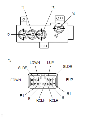 | | *1 | Slide Switch | | *2 | Front Vertical Switch | | *3 | Lifter Switch | | *4 | Reclining Switch | | *a | Component without harness connected (Front Power Seat Switch LH) | | |
2. INSPECT FRONT POWER SEAT SWITCH RH (w/o Memory)
| (a) Measure the resistance according to the value(s) in the tables below. Standard Resistance (Slide Switch): | Tester Connection | Switch Condition | Specified Condition | | 2 (SLDF) - 13 (B) | Front position | Below 1 Ω | | 5 (SLDR) - 10 (E) | | 2 (SLDF) - 10 (E) | Neutral | Below 1 Ω | | 5 (SLDR) - 10 (E) | | 2 (SLDF) - 10 (E) | Rear position | Below 1 Ω | | 5 (SLDR) - 13 (B) | Standard Resistance (Front Vertical Switch): | Tester Connection | Switch Condition | Specified Condition | | 6 (FUP) - 13 (B) | Up position | Below 1 Ω | | 1 (FDWN) - 10 (E) | | 6 (FUP) - 10 (E) | Neutral | Below 1 Ω | | 1 (FDWN) - 10 (E) | | 6 (FUP) - 10 (E) | Down position | Below 1 Ω | | 1 (FDWN) - 13 (B) | Standard Resistance (Lifter Switch): | Tester Connection | Switch Condition | Specified Condition | | 4 (LUP) - 13 (B) | Up position | Below 1 Ω | | 3 (LDWN) - 10 (E) | | 4 (LUP) - 10 (E) | Neutral | Below 1 Ω | | 3 (LDWN) - 10 (E) | | 4 (LUP) - 10 (E) | Down position | Below 1 Ω | | 3 (LDWN) - 13 (B) | Standard Resistance (Reclining Switch): | Tester Connection | Switch Condition | Specified Condition | | 11 (RCLF) - 13 (B) | Front position | Below 1 Ω | | 12 (RCLR) - 10 (E) | | 11 (RCLF) - 10 (E) | Neutral | Below 1 Ω | | 12 (RCLR) - 10 (E) | | 11 (RCLF) - 10 (E) | Rear position | Below 1 Ω | | 12 (RCLR) - 13 (B) | If the result is not as specified, replace the front power seat switch RH. | 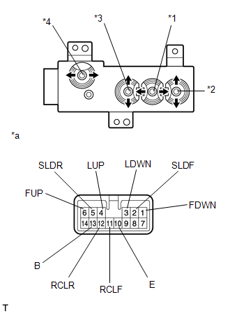 | | *1 | Slide Switch | | *2 | Front Vertical Switch | | *3 | Lifter Switch | | *4 | Reclining Switch | | *a | Component without harness connected (Front Power Seat Switch RH) | | |
READ NEXT:
INSTALLATION CAUTION / NOTICE / HINT HINT:
Use the same procedure for the RH and LH sides.
The procedure listed below is for the LH side.
PROCEDURE 1. INSTALL FRONT POWER SEAT SWITCH LH (a) In
COMPONENTS ILLUSTRATION *A for Front Side - - *1 CONSOLE ARMREST ASSEMBLY *2 COWL SIDE TRIM BOARD LH *3 DOOR SCUFF PLATE ASSEMBLY LH *4 INSTRUMENT SIDE PANEL LH *5
SEE MORE:
DESCRIPTION This DTC is stored if the rear television camera assembly judges that there is an internal malfunction as a result of its self check. HINT: The rear television camera assembly stores different types of information during initialization. If the rear television camera assembly cannot read
CUSTOMIZE PARAMETERS CUSTOMIZE ROAD SIGN ASSIST SYSTEM NOTICE: Be sure to make a note of the current settings before customizing. (a) Customizing with the multi-information display (1) Turn the power switch on (IG). (2) Using the steering pad switches, change the customize settings. HINT: Each item
© 2016-2026 Copyright www.lexunx.com

 Installation