Lexus NX: Components
COMPONENTS
ILLUSTRATION
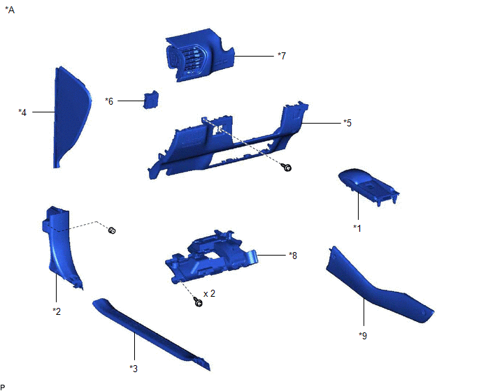
| *A | for Front Side | - | - |
| *1 | CONSOLE ARMREST ASSEMBLY | *2 | COWL SIDE TRIM BOARD LH |
| *3 | DOOR SCUFF PLATE ASSEMBLY LH | *4 | INSTRUMENT SIDE PANEL LH |
| *5 | LOWER NO. 1 INSTRUMENT PANEL FINISH PANEL | *6 | NO. 1 FOLD SEAT SWITCH ASSEMBLY |
| *7 | NO. 1 INSTRUMENT PANEL SAFETY PAD SUB-ASSEMBLY | *8 | NO. 1 INSTRUMENT PANEL UNDER COVER SUB-ASSEMBLY |
| *9 | UPPER NO. 2 CONSOLE PANEL GARNISH | - | - |
ILLUSTRATION
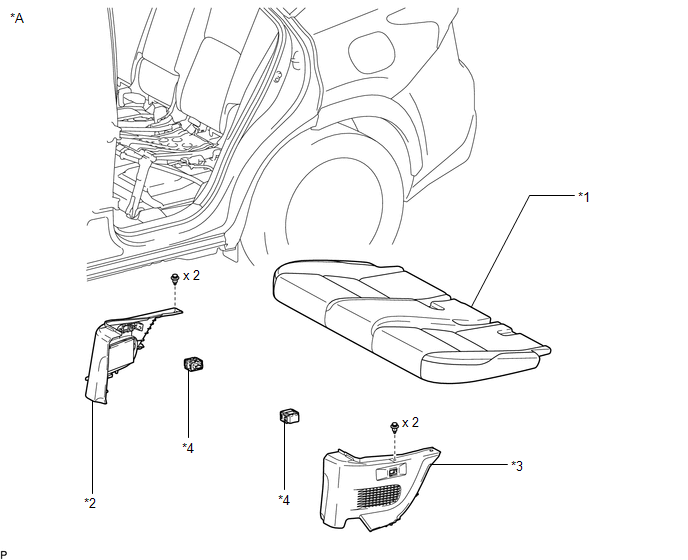
| *A | for Rear Seat | - | - |
| *1 | BENCH TYPE REAR SEAT CUSHION ASSEMBLY | *2 | NO. 2 BATTERY SERVICE COVER BOARD |
| *3 | NO. 3 BATTERY SERVICE COVER BOARD | *4 | REAR POWER SEAT SWITCH |
ILLUSTRATION
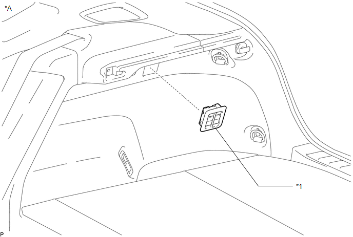
| *A | for Rear Side | - | - |
| *1 | NO. 2 FOLD SEAT SWITCH ASSEMBLY | - | - |
READ NEXT:
 Removal
REMOVAL PROCEDURE 1. REMOVE CONSOLE ARMREST ASSEMBLY (for Front Side) Click here 2. REMOVE UPPER NO. 2 CONSOLE PANEL GARNISH (for Front Side) Click here 3. REMOVE DOOR SCUFF PLATE ASSEMBLY LH
Inspection
INSPECTION PROCEDURE 1. INSPECT NO. 1 FOLD SEAT SWITCH ASSEMBLY (for Front Side) (a) Measure the resistance according to the value(s) in the table below. Standard Resistance: Tester Connection
Installation
INSTALLATION PROCEDURE 1. INSTALL NO. 2 FOLD SEAT SWITCH ASSEMBLY (for Rear Side) (a) Connect the connector. (b) Attach the 2 claws to install the No. 2 fold seat switch assembly.
SEE MORE:
Driving the vehicle
The specified procedures should be
observed to ensure safe driving:
Driving procedure
■ Starting the hybrid system
■ Driving
1. With the brake pedal depressed,
shift the shift lever to D.
2. Release the parking brake.
If the parking brake is in automatic mode,
the parking brake is rele
Blind Spot Monitor Slave Module Beam Axis Inspection Incomplete (C1ABC)
DESCRIPTION This DTC is stored when a beam axis inspection has not been performed for the blind spot monitor sensor RH. HINT: This DTC is always stored after replacing a blind spot monitor sensor. The purpose of this DTC is to ensure that beam axis inspection is performed. Completing the beam axis i
© 2016-2026 Copyright www.lexunx.com
