Lexus NX: Inspection
INSPECTION
PROCEDURE
1. INSPECT NO. 1 FOLD SEAT SWITCH ASSEMBLY (for Front Side)
| (a) Measure the resistance according to the value(s) in the table below. Standard Resistance:
If the result is not as specified, replace the No. 1 fold seat switch assembly. |
|
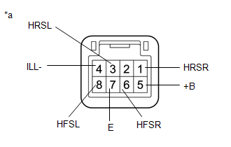
(b) Apply auxiliary battery voltage to the switch connector and check that the No. 1 fold seat switch assembly illuminates.
OK:
| Condition | Specified Condition |
|---|---|
| Auxiliary battery positive (+) → Terminal 5 (+B) Auxiliary battery negative (-) → Terminal 4 (ILL-) | Illumination illuminates |
If the result is not as specified, replace the No. 1 fold seat switch assembly.
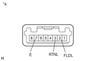
2. INSPECT REAR POWER SEAT SWITCH (for Rear Seat)
(a) for LH Side:
| (1) Measure the resistance according to the value(s) in the table below. Standard Resistance:
If the result is not as specified, replace the rear power seat switch. |
|
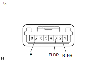
(b) for RH Side:
| (1) Measure the resistance according to the value(s) in the table below. Standard Resistance:
If the result is not as specified, replace the rear power seat switch. |
|
3. INSPECT NO. 2 FOLD SEAT SWITCH ASSEMBLY (for Rear Side)
| (a) Measure the resistance according to the value(s) in the table below. Standard Resistance:
If the result is not as specified, replace the No. 2 fold seat switch assembly. |
|
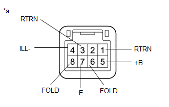
(b) Apply auxiliary battery voltage to the switch connector and check that the No. 2 fold seat switch assembly illuminates.
OK:
| Condition | Specified Condition |
|---|---|
| Auxiliary battery positive (+) → Terminal 5 (+B) Auxiliary battery negative (-) → Terminal 4 (ILL-) | Illumination illuminates |
If the result is not as specified, replace the No. 2 fold seat switch assembly.
READ NEXT:
 Installation
INSTALLATION PROCEDURE 1. INSTALL NO. 2 FOLD SEAT SWITCH ASSEMBLY (for Rear Side) (a) Connect the connector. (b) Attach the 2 claws to install the No. 2 fold seat switch assembly.
Precaution
PRECAUTION POWER FOLDING SEAT FUNCTION HANDLING PRECAUTIONS NOTICE:
When operating the rear power seat, make sure nothing is in the path of movement.
When operating the rear power seat, do not al
SEE MORE:
Precaution
PRECAUTION PRECAUTIONS WHEN USING TECHSTREAM (a) When using the Techstream with the vehicle power switch off, connect the Techstream to the DLC3 and turn a courtesy light switch on and off at intervals of 1.5 seconds or less until communication between the Techstream and the vehicle begins. Then sel
Removal
REMOVAL PROCEDURE 1. REMOVE REAR SEAT ASSEMBLY (for Manual Seat) Click here 2. REMOVE REAR SEAT ASSEMBLY (for Power Seat) Click here 3. REMOVE TONNEAU COVER ASSEMBLY Click here 4. REMOVE DECK BOARD ASSEMBLY Click here 5. REMOVE NO. 2 DECK BOARD SUB-ASSEMBLY Click here 6. REMOVE NO. 3 DECK
