Lexus NX: Inspection
INSPECTION
PROCEDURE
1. INSPECT SEPARATE TYPE REAR SEATBACK COVER RH (REAR SEATBACK HEATER ASSEMBLY RH) (for RH Side)
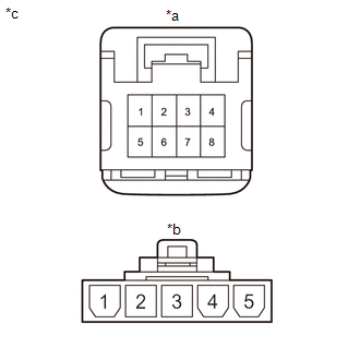
| (a) Check the separate type rear seatback cover RH (rear seatback heater assembly RH). (1) Measure the resistance according to the value(s) in the table below. Standard Resistance:
If the result is not as specified, replace the separate type rear seatback cover RH (rear seatback heater assembly RH). |
|
2. INSPECT SEPARATE TYPE REAR SEATBACK COVER LH (REAR SEATBACK HEATER ASSEMBLY LH) (for LH Side)
| (a) Check the separate type rear seatback cover LH (rear seatback heater assembly LH). (1) Measure the resistance according to the value(s) in the table below. Standard Resistance:
If the result is not as specified, replace the separate type rear seatback cover LH (rear seatback heater assembly LH). |
|
READ NEXT:
 Installation
INSTALLATION CAUTION / NOTICE / HINT CAUTION: Wear protective gloves. Sharp areas on the parts may injure your hands. PROCEDURE 1. INSTALL SEPARATE TYPE REAR SEATBACK COVER LH (REAR SEATBACK HEATER AS
Components
COMPONENTS ILLUSTRATION *A for RH Side - - *1 REAR NO. 1 SEAT HEADREST SUPPORT ASSEMBLY *2 REAR SEAT CUSHION MOULDING RH *3 REAR SEAT CUSHION MOULDING RH *4 REAR SEAT HEA
SEE MORE:
Open in One Side of Bus 3 Branch Line
DESCRIPTION When the CAN bus main lines are normal (no open, short to ground, short to +B or short between lines) and there is an ECU or sensor on the "Communication Bus Check" screen that is indicated as not communicating or whose connection status on the "Communication Bus Check" screen changes in
Removal
REMOVAL PROCEDURE 1. REMOVE REAR SEAT ASSEMBLY (a) for Power Seat: Click here (b) for Manual Seat: Click here 2. REMOVE REAR FLOOR FINISH PLATE Click here 3. REMOVE REAR DOOR OPENING TRIM WEATHERSTRIP LH Click here 4. REMOVE UPPER DECK TRIM SIDE BOARD LH Click here 5. REMOVE ROPE H
