Lexus NX: Installation
INSTALLATION
CAUTION / NOTICE / HINT
HINT:
Perform "Inspection After Repairs" after replacing the engine coolant temperature sensor.
Click here .gif)
PROCEDURE
1. INSTALL ENGINE COOLANT TEMPERATURE SENSOR
HINT:
Perform "Inspection After Repairs" after replacing the engine coolant temperature sensor.
Click here
| (a) Using a 19 mm ball joint lock nut wrench, install a new gasket and engine coolant temperature sensor. Torque: Specified tightening torque 19.6 N*m (200 kgf*cm, 14 ft.*lbf) HINT:
|
|
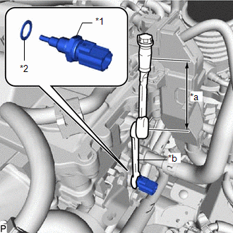
(b) Connect the 2 ground wires with the 2 bolts.
Torque:
8.4 N·m {86 kgf·cm, 74 in·lbf}
(c) Connect the engine coolant temperature sensor connector.
2. ADD ENGINE COOLANT
Click here
3. INSPECT FOR COOLANT LEAK
Click here
4. INSTALL NO. 1 ENGINE COVER SUB-ASSEMBLY
Click here
READ NEXT:
 Heated Oxygen Sensor
ComponentsCOMPONENTS ILLUSTRATION *1 FRONT EXHAUST PIPE SUB-ASSEMBLY *2 HEATED OXYGEN SENSOR *3 COMPRESSION SPRING *4 GASKET N*m (kgf*cm, ft.*lbf): Specified torque * F
Ignition Coil And Spark Plug
ComponentsCOMPONENTS ILLUSTRATION *1 IGNITION COIL ASSEMBLY *2 NO. 1 ENGINE COVER SUB-ASSEMBLY *3 SPARK PLUG - - N*m (kgf*cm, ft.*lbf) : Specified torque - - Remova
SEE MORE:
Diagnosis System
DIAGNOSIS SYSTEM DESCRIPTION (a) Blind spot monitor data and Diagnostic Trouble Codes (DTCs) can be read from the Data Link Connector 3 (DLC3) of the vehicle. When the system seems to be malfunctioning, use the Techstream to check for malfunctions and perform repairs. CHECK DLC3 (a) Check the DLC3.
Removal
REMOVAL PROCEDURE 1. PRECAUTION NOTICE: After turning the power switch off, there may be a waiting time before disconnecting the negative (-) auxiliary battery terminal. Click here 2. REMOVE DECK BOARD ASSEMBLY Click here 3. REMOVE NO. 3 DECK BOARD SUB-ASSEMBLY Click here 4. REMOVE REAR DECK F
