Lexus NX: Installation
INSTALLATION
CAUTION / NOTICE / HINT
HINT:
Perform "Inspection After Repairs" after replacing the throttle with motor body assembly.
Click here .gif)
PROCEDURE
1. INSTALL THROTTLE WITH MOTOR BODY ASSEMBLY
HINT:
Perform "Inspection After Repairs" after replacing the throttle with motor body assembly.
Click here
(a) Install a new gasket to the intake manifold.
HINT:
Check that the gasket is securely fitted into the groove on the intake manifold.
(b) Install the fuel hose bracket and throttle with motor body assembly with the 4 bolts.
Torque:
10 N·m {102 kgf·cm, 7 ft·lbf}
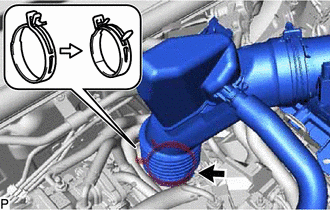
(c) Connect the No. 2 water by-pass hose and No. 3 water by-pass hose to the throttle with motor body assembly, and secure them with the 2 clamps.
(d) Connect the throttle with motor body assembly connector.
(e) Connect the fuel tube sub-assembly and No. 2 fuel vapor feed hose to the fuel hose clamp.
2. INSTALL AIR CLEANER CAP AND HOSE
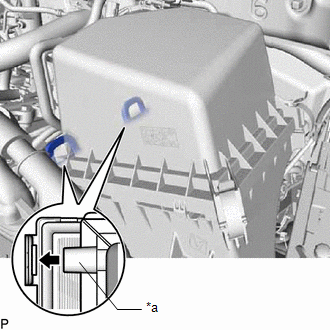
| (a) Connect the air cleaner cap and hose to the throttle with motor body assembly and unlock the hose clamp to install it. |
|
| (b) Install the 2 hinges first, and then install the air cleaner cap sub-assembly with the 2 clamps. |
|
(c) Connect the 3 wire harness clamps.
(d) Connect the fuel vapor feed hose and No. 2 fuel vapor feed hose to the purge valve, and secure them with the 2 clamps.
(e) Connect the purge valve connector.
(f) Connect the ventilation hose assembly to the cylinder head cover sub-assembly, and secure the clip.
(g) Connect the mass air flow meter sub-assembly connector.
3. ADD ENGINE COOLANT
Click here
4. INSPECT FOR COOLANT LEAK
Click here
5. INSTALL NO. 1 ENGINE COVER SUB-ASSEMBLY
Click here
6. PERFORM INITIALIZATION
NOTICE:
Perform the following procedure after replacing the throttle with motor body assembly or any throttle with motor body assembly components. The following procedure should also be performed if the throttle with motor body assembly is cleaned.
(a) Turn the power switch on (IG) without operating the accelerator pedal.
NOTICE:
If the accelerator pedal is operated, perform the above steps again.
(b) Connect the Techstream to the DLC3 and clear the DTCs.
Click here
(c) Perform the "Inspection After Repairs".
Click here
(d) Put the engine in inspection mode (maintenance mode).
Click here
(e) Start the engine and check that the MIL is not illuminated. After the engine is warmed up, check that the idle speed is within the specified range when the A/C is switched off.
Standard:
| Condition | Engine Idle Speed |
|---|---|
| A/C switched off | 950 to 1050 rpm |
NOTICE:
- Be sure to perform this step with all accessories off.
- Make sure that the shift lever is in P.
(f) Enter the following menus: Powertrain / Engine and ETC / Data List / Throttle Sensor Position. Fully depress the accelerator pedal and check that the value is 60% or more.
Powertrain > Engine and ECT > Data List| Tester Display |
|---|
| Throttle Sensor Position |
(g) Perform a road test and confirm that there are no abnormalities.
READ NEXT:
 Components
COMPONENTS ILLUSTRATION *1 AIR CLEANER CAP SUB-ASSEMBLY *2 AIR CLEANER CASE SUB-ASSEMBLY *3 AIR CLEANER FILTER ELEMENT SUB-ASSEMBLY *4 ENGINE WIRE *5 FAN AND GENERATOR V BELT
SEE MORE:
Components
COMPONENTS ILLUSTRATION *1 COWL SIDE TRIM BOARD LH *2 DOOR SCUFF PLATE ASSEMBLY LH *3 NO. 1 INSTRUMENT PANEL UNDER COVER SUB-ASSEMBLY *4 STOP LIGHT SWITCH ASSEMBLY *5 STOP LIGHT SWITCH MOUNTING ADJUSTER - - N*m (kgf*cm, ft.*lbf): Specified torque * For use wi
Fail-safe Chart
FAIL-SAFE CHART Constant Speed Control Mode: Condition Multi-information Display Master Warning Light Cruise Control Indicator Warning Buzzer When the following condition(s) occurs while the vehicle is in motion during cruise control, the system clears the set vehicle speed and cancel
