Lexus NX: Replacement
REPLACEMENT
PROCEDURE
1. REMOVE NO. 1 ENGINE UNDER COVER
Click here .gif)
2. DRAIN COOLANT (for Inverter Coolant)
NOTICE:
Collect the drained coolant and measure its volume to establish a benchmark. When adding coolant, make sure to add more coolant than the measured amount.
(a) Remove the inverter reserve tank cap.
CAUTION:
To avoid the danger of being burned, do not remove the inverter reserve tank cap while the coolant for the inverter is still hot.
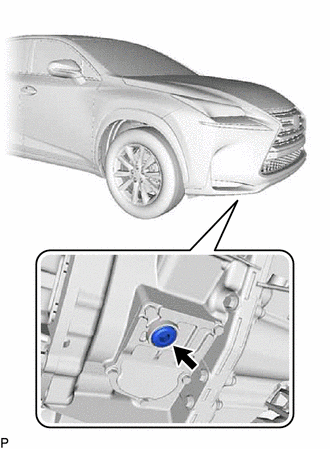
| (b) Using a 10 mm hexagon wrench, remove the drain plug at the position shown in the illustration, and drain the coolant. CAUTION: Use caution when handling coolant immediately after driving or in summer because it may be hot. |
|
(c) Install the drain plug with a new gasket.
Torque:
39.2 N·m {400 kgf·cm, 29 ft·lbf}
(d) Measure the volume of coolant discharged from the drain.
3. ADD COOLANT (for Inverter Coolant)
NOTICE:
If the vehicle is driven with air in the coolant system, damage may occur and the following DTCs may be stored.
| DTC No. | Detection Item |
|---|---|
| P0A01-726 | Motor Electronics Coolant Temperature Sensor Circuit Range / Performance |
| P0A04-725 | Motor Electronics Coolant Temperature Sensor Circuit Intermittent |
| P0A08-264 | DC / DC Converter Status Circuit |
| P0A78-284 | Drive Motor "A" Inverter Performance |
| P0A78-286 | Drive Motor "A" Inverter Performance |
| P0A7A-322 | Generator Inverter Performance |
| P0A7A-324 | Generator Inverter Performance |
| P0A93-346 | Inverter Cooling System Performance |
| P0A94-553 | DC / DC Converter Performance |
| P0A94-557 | DC / DC Converter Performance |
| P0AEE-277 | Motor Inverter Temperature Sensor "A" Circuit Range / Performance |
| P0AF1-276 | Drive Motor Inverter Temperature Sensor "A" Circuit Intermittent / Erratic |
| P0BCD-315 | Generator Inverter Temperature Sensor Circuit Range / Performance |
| P0BD0-314 | Generator Inverter Temperature Sensor Circuit Intermittent / Erratic |
| P0C39-626 | DC / DC Converter Temperature Sensor "A" Range / Performance |
| P0C3C-625 | DC / DC Converter Temperature Sensor "A" Intermittent / Erratic |
| P0C3E-628 | DC / DC Converter Temperature Sensor "B" Range / Performance |
| P0C41-627 | DC / DC Converter Temperature Sensor "B" Intermittent / Erratic |
| P0C73-776 | Motor Electronics Coolant Pump "A" Control Performance |
(a) Slowly pour coolant into the inverter reserve tank until it reaches the FULL line.
NOTICE:
To prevent foreign matter such as dust or dirt from entering the cooling system, make sure to confirm that the container used to add coolant is clean and free of foreign matter such as dust or dirt.
Standard Capacity:
3.1 liters (3.3 US qts, 2.7 Imp. qts.)
(b) When using the Techstream:
(1) Connect the Techstream to the DLC3.
(2) Turn the power switch on (IG).
(3) Enter the following menus: Powertrain / Hybrid Control / Active Test / Activate the (Inverter) Water Pump.
Powertrain > Hybrid Control > Active Test| Tester Display |
|---|
| Activate the (Inverter) Water Pump |
(4) Keep the coolant at the FULL line in the inverter reserve tank to compensate for the drop in coolant level when the air bleeds.
Standard:
Air bleeding from the inverter cooling system is completed when the noise made by the inverter water pump assembly becomes smaller and the circulation of coolant in the reserve tank improves.
HINT:
- If free spinning of the inverter water pump is detected for approximately 5 seconds, fail-safe control will be activated to suspend the operation of the pump for approximately 15 seconds and resume operation for approximately 4 seconds repeatedly. Operation of the inverter water pump will return to normal if coolant is added.
- A loud noise made by the inverter water pump assembly and poor circulation of coolant in the inverter reserve tank indicates that there is air in the cooling system.
(c) When not using the Techstream:
(1) Turn the power switch on (READY). [*1]
(2) Turn the power switch off and add coolant to the FULL line because the coolant level drops as the air bleeds. [*2]
NOTICE:
- Be sure to turn the power switch off before adding TOYOTA Super Long Life Coolant (SLLC).
- Do not work on the components in the engine compartment while the power switch is on (READY) as the engine will operate intermittently.
(3) Repeat steps [*1] and [*2] until air bleeding from the cooling system is completed.
Standard:
Air bleeding from the inverter cooling system is completed when the noise made by the inverter water pump assembly becomes smaller and the circulation of coolant in the inverter reserve tank improves.
HINT:
A loud noise made by the inverter water pump assembly and poor circulation of coolant in the inverter reserve tank indicates that there is air in the cooling system.
(d) After the air is completely bled from the cooling system, add coolant to the FULL line of the inverter reserve tank.
NOTICE:
Collect the drained coolant and measure its volume to establish a benchmark. When adding coolant, make sure to add more coolant than the measured amount.
(e) Tighten the inverter reserve tank cap.
4. INSPECT FOR COOLANT LEAK (for Inverter Coolant)
Click here
5. INSTALL NO. 1 ENGINE UNDER COVER
Click here
READ NEXT:
 Frame Wire
ComponentsCOMPONENTS ILLUSTRATION *1 AIR CLEANER CAP SUB-ASSEMBLY *2 AIR CLEANER CASE SUB-ASSEMBLY *3 AIR CLEANER FILTER ELEMENT SUB-ASSEMBLY *4 CONNECTOR COVER ASSEMBLY *5
Charging
CHARGING PROCEDURE 1. PRECAUTION CAUTION: Be sure to read Precaution thoroughly before servicing. Click here 2. INSPECT AUXILIARY BATTERY VOLTAGE Click here 3. PREPARATION FOR HV BATTERY CHARGING
SEE MORE:
Vehicle Control History
VEHICLE CONTROL HISTORY NOTICE: When checking the vehicle control history, first record the output codes and after clearing the history, check the output history again. CHECK VEHICLE CONTROL HISTORY (FRONT CAMERA SYSTEM) (a) Connect the Techstream to the DLC3. (b) Turn the power switch on (IG). (c)
Removal
REMOVAL PROCEDURE 1. REMOVE NO. 1 ENGINE UNDER COVER ASSEMBLY Click here 2. DRAIN COOLANT (for Inverter Coolant) Click here 3. REMOVE NO. 2 MOTOR WATER JACKET COVER ASSEMBLY (a) Remove the 5 bolts. (b) Insert the blade of an oil pan seal cutter between the transaxle housing. Cut
