Lexus NX: Installation
INSTALLATION
CAUTION / NOTICE / HINT
HINT:
- Use the same procedure for the RH and LH sides.
- The procedure listed below is for the LH side.
PROCEDURE
1. INSTALL FRONT FENDER MOULDING SUB-ASSEMBLY LH
HINT:
When installing the front fender moulding sub-assembly LH, heat the vehicle body and front fender moulding sub-assembly LH using a heat light.
Standard:
| Item | Temperature |
|---|---|
| Vehicle Body | 40 to 60°C (104 to 140°F) |
| Front Fender Moulding Sub-assembly LH | 20 to 30°C (68 to 86°F) |
NOTICE:
Do not heat the vehicle body and front fender moulding sub-assembly LH excessively.
(a) Clean the vehicle body surface.
(1) Using a heat light, heat the vehicle body surface.
(2) Remove the double-sided tape from the vehicle body.
(3) Wipe off any tape adhesive residue with cleaner.
(b) Install the front fender moulding sub-assembly LH.
(1) Using a heat light, heat the vehicle body.
(2) Remove the peeling paper from the face of the No. 1 moulding tape and No. 5 moulding tape.
HINT:
After removing the peeling paper, keep the exposed adhesive free from foreign matter.
(c) Attach the 5 claws and 8 clips so as to apply the No. 1 moulding tape and No. 2 moulding tape and install the front fender moulding sub-assembly LH as shown in the illustration.
HINT:
Press the front fender moulding sub-assembly LH firmly to install it.
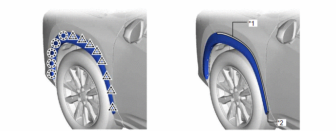
| *1 | No. 1 Moulding Tape (Double-sided Tape) | *2 | No. 2 Moulding Tape (Double-sided Tape) |
(d) Using a 4 mm hexagon socket wrench, install the 2 hexagon screws.
(e) Install the 6 clips.
READ NEXT:
 Components
COMPONENTS ILLUSTRATION *1 QUARTER OUTSIDE MOULDING SUB-ASSEMBLY LH - - ILLUSTRATION *1 NO. 5 MOULDING TAPE *2 REAR LOWER QUARTER MOULDING PROTECTOR LH ● Non-reusable pa
Removal
REMOVAL CAUTION / NOTICE / HINT HINT:
Use the same procedure for the RH and LH sides.
The procedure listed below is for the LH side.
PROCEDURE 1. REMOVE QUARTER OUTSIDE MOULDING SUB-ASSEMBLY L
SEE MORE:
On-vehicle Inspection
ON-VEHICLE INSPECTION PROCEDURE 1. INSPECT REAR WIPER MOTOR ASSEMBLY (a) Check the automatic stop (park) position. (1) Operate the rear wiper motor assembly, and then stop the operation. Check the wiper arm automatic stop (park) position. OK: Rear wiper arm stops at the position shown in the ill
Drive Motor "A" Position Sensor Circuit Range / Performance (P0A40-506,P0A40-808)
DTC SUMMARY MALFUNCTION DESCRIPTION These DTCs indicate that a large current flowed in the inverter for the motor. The cause of this malfunction may be one of the following: Area Main Malfunction Description Step Inverter low-voltage circuit The connectors are not connected properly 3
