Lexus NX: Installation
INSTALLATION
CAUTION / NOTICE / HINT
HINT:
- Use the same procedure for the RH and LH sides.
- The procedure described below is for the LH side.
PROCEDURE
1. INSTALL HEADLIGHT ASSEMBLY LH
| (a) w/o Headlight ECU: Connect the 2 connectors and attach the wire harness clamp. |
|
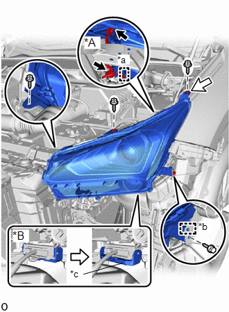
(b) w/ Headlight ECU:
Connect the connector and lock the connector lock lever.
(c) Attach the guide to set the headlight assembly LH.
(d) Connect the seat of the screw at the location indicated by the white arrow shown in the illustration and set the headlight assembly LH in place.
(e) Install the bolt and 3 screws.
Torque:
for Bolt :
5.4 N·m {55 kgf·cm, 48 in·lbf}
2. INSTALL FRONT BUMPER ASSEMBLY
(a) except Sport Package:
Click here .gif)
(b) for Sport Package:
Click here
3. ADJUST HEADLIGHT AIMING
Click here
4. PERFORM INITIALIZATION (When Replacing The Headlight Assembly LH or Headlight Light Control ECU Sub-assembly LH)
NOTICE:
-
If any of the work in the table below has been performed, vehicle information registration and initialization of the headlight ECU sub-assembly LH is necessary.
Click here
Performed Work or System Condition
Necessary Procedures
Replacement of the headlight ECU sub-assembly LH
Vehicle information registration for the headlight ECU sub-assembly LH
Initialization of the headlight ECU sub-assembly LH
Replacement of the headlight assembly LH
Vehicle information registration for the headlight ECU sub-assembly LH
Initialization of the headlight ECU sub-assembly LH
- A new headlight ECU sub-assembly LH cannot operate until the vehicle information is registered.
- After replacing the headlight ECU sub-assembly LH, it is necessary to register the vehicle information and then perform initialization.
- Even if the headlight ECU sub-assembly RH is replaced with a new one, vehicle information registration and initialization are not necessary.
- Vehicle information registration must be performed with the multiplex network body ECU (main body ECU) and ECM connected via CAN communication.
READ NEXT:
 Repair
REPAIR CAUTION / NOTICE / HINT HINT:
Use the same procedure for the RH and LH sides.
The procedure listed below is for the LH side.
If the installation area of the headlight assembly is damaged
Components
COMPONENTS ILLUSTRATION *1 DECK FLOOR BOX LH *2 NO. 3 DECK BOARD SUB-ASSEMBLY *3 REAR DECK FLOOR BOX *4 AUXILIARY BATTERY NEGATIVE TERMINAL N*m (kgf*cm, ft.*lbf): Specified
SEE MORE:
On-vehicle Inspection
ON-VEHICLE INSPECTION PROCEDURE 1. INSPECT COOLING FAN MOTOR (a) Disconnect the cooling fan motor connector. (b) Check that the fan rotates smoothly by hand. (c) Check that the cooling fan motor turns smoothly when the battery is connected to the cooling fan motor connector. Click here
Lost Communication with Multi-axis Acceleration Sensor Module Missing Message (U012587,U012987,U014087,U029387)
DESCRIPTION DTC No. Detection Item DTC Detection Condition Trouble Area DTC Output from U012587 Lost Communication with Multi-axis Acceleration Sensor Module Missing Message Communication stop occurs between the forward recognition camera and airbag ECU assembly continuously for 5
