Lexus NX: Light Sensor Circuit Malfunction (B1244)
DESCRIPTION
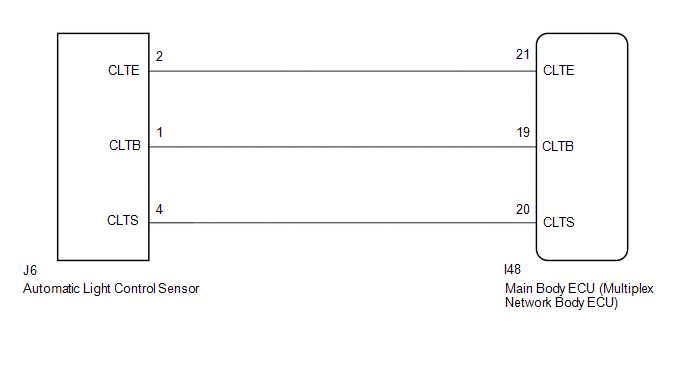
The automatic light control sensor detects ambient light, converts it into an electrical signal and outputs it to the main body ECU (multiplex network body ECU). The main body ECU (multiplex network body ECU) turns the headlights and taillights on or off according to the signal.
The main body ECU (multiplex network body ECU) outputs DTC B1244.
| DTC No. | Detection Item | DTC Detection Condition | Trouble Area |
|---|---|---|---|
| B1244 | Light Sensor Circuit Malfunction |
|
|
WIRING DIAGRAM
CAUTION / NOTICE / HINT
NOTICE:
- Recognition code registration is necessary when replacing the main body ECU (multiplex network body ECU).
- If the main body ECU (multiplex network body ECU) is replaced, refer to Registration.
PROCEDURE
| 1. | CLEAR DTC |
(a) Clear the DTCs.
Click here .gif)
|
.gif)
| 2. | CHECK FOR DTC |
(a) Check for DTCs.
Click here
| DTC B1244 output does not occur | .gif) | USE SIMULATION METHOD TO CHECK |
|
| 3. | READ VALUE USING TECHSTREAM (LIGHT SENSOR ILLUMINANCE) |
(a) Using the Techstream, read the Data List.
Click here
| Tester Display | Measurement Item | Range | Normal Condition | Diagnostic Note |
|---|---|---|---|---|
| Light Sensor Illuminance | Light control sensor illuminance | 0 to 17600 lx | Value is output according to ambient light level | - |
| Tester Display |
|---|
| Light Sensor Illuminance |
OK:
The display is as specified in the normal condition column.
| OK | | REPLACE MAIN BODY ECU (MULTIPLEX NETWORK BODY ECU) |
|
| 4. | CHECK HARNESS AND CONNECTOR (MAIN BODY ECU - AUTOMATIC LIGHT CONTROL SENSOR) |
(a) Disconnect the I48 main body ECU (multiplex network body ECU) connector.
(b) Disconnect the J6 automatic light control sensor connector.
(c) Measure the resistance according to the value(s) in the table below.
Standard Resistance:
| Tester Connection | Condition | Specified Condition |
|---|---|---|
| I48-21 (CLTE) - J6-2 (CLTE) | Always | Below 1 Ω |
| I48-19 (CLTB) - J6-1 (CLTB) | Always | Below 1 Ω |
| I48-20 (CLTS) - J6-4 (CLTS) | Always | Below 1 Ω |
| I48-21 (CLTE) - Body ground | Always | 10 kΩ or higher |
| I48-19 (CLTB) - Body ground | Always | 10 kΩ or higher |
| I48-20 (CLTS) - Body ground | Always | 10 kΩ or higher |
| NG | | REPAIR OR REPLACE HARNESS OR CONNECTOR |
|
| 5. | CHECK MAIN BODY ECU (MULTIPLEX NETWORK BODY ECU) |
| (a) Remove the instrument panel junction block assembly and main body ECU (multiplex network body ECU) as a unit with the connectors still connected. Click here |
|
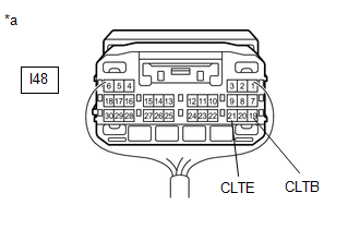
(b) Measure the voltage according to the value(s) in the table below.
Standard Voltage:
| Tester Connection | Switch Condition | Specified Condition |
|---|---|---|
| I48-19 (CLTB) - I48-21 (CLTE) | Power switch off | Below 1 V |
| Power switch on (IG) | 11 to 14 V |
| NG | | REPLACE MAIN BODY ECU (MULTIPLEX NETWORK BODY ECU) |
|
| 6. | CHECK AUTOMATIC LIGHT CONTROL SENSOR |
(a) Check the automatic light control sensor.
Click here
| OK | | REPLACE MAIN BODY ECU (MULTIPLEX NETWORK BODY ECU) |
| NG | | REPLACE AUTOMATIC LIGHT CONTROL SENSOR |
READ NEXT:
 LED Headlight LH Circuit Malfunction (B2430,B2431)
DESCRIPTION The illumination of the low beam headlights is controlled by the main body ECU (multiplex network body ECU). When the headlights are turned on, the main body ECU (multiplex network body EC
Lost Communication with Multi-axis Acceleration Sensor Module Missing Message (U012587,U012987,U014087,U029387)
DESCRIPTION DTC No. Detection Item DTC Detection Condition Trouble Area DTC Output from U012587 Lost Communication with Multi-axis Acceleration Sensor Module Missing Message Communi
Lost Communication with Cruise Control Front Distance Range Sensor Missing Message (U023587)
DESCRIPTION DTC No. Detection Item DTC Detection Condition Trouble Area DTC Output from Note U023587 Lost Communication with Cruise Control Front Distance Range Sensor Missing Messa
SEE MORE:
Removal
REMOVAL PROCEDURE 1. REMOVE SYMBOL EMBLEM HINT: When removing the symbol emblem, heat the back door outside garnish sub-assembly and symbol emblem using a heat light. Standard: Item Temperature Back Door Outside Garnish Sub-assembly 40 to 60°C (104 to 140°F) Symbol Emblem 20 to 3
Route cannot be Calculated
PROCEDURE 1. SET DESTINATION (a) Set another destination and check if the system can calculate the route correctly. OK: Route can be correctly calculated. OK NORMAL OPERATION NG PROCEED TO NEXT SUSPECTED AREA SHOWN IN PROBLEM SYMPTOMS TABLE
