Lexus NX: Lost Communication with Cruise Control Front Distance Range Sensor Missing Message (U023587)
DESCRIPTION
| DTC No. | Detection Item | DTC Detection Condition | Trouble Area | DTC Output from | Note |
|---|---|---|---|---|---|
| U023587 | Lost Communication with Cruise Control Front Distance Range Sensor Missing Message |
|
| Front Recognition Camera (Front Lighting Control) | - |
| Pattern | DTC output part name (Display on Techstream) | Suspected Area (Malfunction Status) |
|---|---|---|
| Forward Recognition Camera (Front Recognition Camera(Front Light Control)) | ||
| U023587 | ||
|
○: DTC is output
-: DTC is not output | ||
| Pattern 1 | ○ | Local bus (Open or short) |
| Millimeter wave radar sensor assembly (Internal malfunction) | ||
| Forward recognition camera (Internal malfunction) | ||
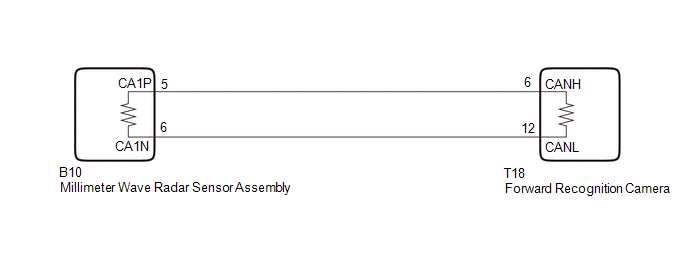
WIRING DIAGRAM
CAUTION / NOTICE / HINT
NOTICE:
- When replacing the millimeter wave radar sensor assembly, always replace it with a new one. If a millimeter wave radar sensor assembly which was installed to another vehicle is used, the information stored in the millimeter wave radar sensor assembly will not match the information from the vehicle. As a result, a DTC may be stored.
-
When the millimeter wave radar sensor assembly has been replaced with a new one, it is necessary to perform millimeter wave radar sensor assembly adjustment and front radar acceleration sensor calibration, and to clear the vehicle control history.
Click here
.gif)
- When replacing the forward recognition camera, always replace it with a new one. If a forward recognition camera which was installed to another vehicle is used, the information stored in the forward recognition camera will not match the information from the vehicle. As a result, a DTC may be stored.
-
If the forward recognition camera has been replaced with a new one, be sure to perform forward recognition camera adjustment.
for sequential recognition: Click here
for one time recognition: Click here
-
After the power switch is turned off, there may be a waiting time before disconnecting the negative (-) auxiliary battery terminal.
Click here
-
When disconnecting and reconnecting the auxiliary battery
Click here
HINT:
When disconnecting and reconnecting the battery, there is an automatic learning function that completes learning when the respective system is used.
Click here
PROCEDURE
| 1. | CHECK CAN BUS WIRE (FORWARD RECOGNITION CAMERA MAIN WIRE) |
(a) Disconnect the cable from the negative (-) auxiliary battery terminal.
(b) Disconnect the T18 forward recognition camera connector.
(c) Measure the resistance according to the value(s) in the table below.
Standard Resistance:
| Tester Connection | Condition | Specified Condition |
|---|---|---|
| T18-6 (CANH) - T18-12 (CANL) | Cable disconnected from negative (-) auxiliary battery terminal | 108 to 132 Ω |
| T18-6 (CANH) - I182-4 (CG) | Cable disconnected from negative (-) auxiliary battery terminal | 200 Ω or higher |
| T18-12 (CANL) - I182-4 (CG) | Cable disconnected from negative (-) auxiliary battery terminal | 200 Ω or higher |
| T18-6 (CANH) - I182-16 (BAT) | Cable disconnected from negative (-) auxiliary battery terminal | 6 kΩ or higher |
| T18-12 (CANL) - I182-16 (BAT) | Cable disconnected from negative (-) auxiliary battery terminal | 6 kΩ or higher |
| NG | .gif) | GO TO STEP 5 |
|
.gif)
| 2. | CHECK MILLIMETER WAVE RADAR SENSOR ASSEMBLY |
(a) Temporarily replace the millimeter wave radar sensor assembly with a new one.
Click here
|
| 3. | CLEAR DTC |
(a) Connect the Techstream to the DLC3.
(b) Turn the power switch on (IG).
(c) Turn the Techstream on.
(d) Enter the following menus: Body Electrical / Front Recognition Camera (Front Lighting Control) / Clear DTCs.
(e) Clear the DTCs.
Body Electrical > Front Recognition Camera (Front Lighting Control) > Clear DTCs
|
| 4. | CHECK FOR DTC |
(a) Connect the Techstream to the DLC3.
(b) Turn the power switch on (IG).
(c) Wait 5 seconds or more.
(d) Turn the Techstream on.
(e) Enter the following menus: Body Electrical / Front Recognition Camera (Front Lighting Control) / Trouble Codes.
(f) Check for DTCs.
Body Electrical > Front Recognition Camera (Front Lighting Control) > Trouble CodesOK:
DTC U023587 is not output.
| OK | | END (MILLIMETER WAVE RADAR SENSOR ASSEMBLY IS DEFECTIVE) |
| NG | | REPLACE FORWARD RECOGNITION CAMERA |
| 5. | CHECK CAN BUS WIRE (MILLIMETER WAVE RADAR SENSOR ASSEMBLY MAIN WIRE) |
(a) Disconnect the B10 millimeter wave radar sensor assembly connector.
(b) Measure the resistance according to the value(s) in the table below.
Standard Resistance:
| Tester Connection | Condition | Specified Condition |
|---|---|---|
| B10-5 (CA1P) - B10-6 (CA1N) | Cable disconnected from negative (-) auxiliary battery terminal | 108 to 132 Ω |
| B10-5 (CA1P) - I182-4 (CG) | Cable disconnected from negative (-) auxiliary battery terminal | 200 Ω or higher |
| B10-6 (CA1N) - I182-4 (CG) | Cable disconnected from negative (-) auxiliary battery terminal | 200 Ω or higher |
| B10-5 (CA1P) - I182-16 (BAT) | Cable disconnected from negative (-) auxiliary battery terminal | 6 kΩ or higher |
| B10-6 (CA1N) - I182-16 (BAT) | Cable disconnected from negative (-) auxiliary battery terminal | 6 kΩ or higher |
| NG | | REPAIR OR REPLACE CAN BUS MAIN WIRE OR CONNECTOR |
|
| 6. | CHECK MILLIMETER WAVE RADAR SENSOR ASSEMBLY |
(a) Temporarily replace the millimeter wave radar sensor assembly with a new one.
Click here
|
| 7. | CLEAR DTC |
(a) Connect the Techstream to the DLC3.
(b) Turn the power switch on (IG).
(c) Turn the Techstream on.
(d) Enter the following menus: Body Electrical / Front Recognition Camera (Front Lighting Control) / Clear DTCs.
(e) Clear the DTCs.
Body Electrical > Front Recognition Camera (Front Lighting Control) > Clear DTCs
|
| 8. | CHECK FOR DTC |
(a) Connect the Techstream to the DLC3.
(b) Turn the power switch on (IG).
(c) Wait 5 seconds or more.
(d) Turn the Techstream on.
(e) Enter the following menus: Body Electrical / Front Recognition Camera (Front Lighting Control) / Trouble Codes.
(f) Check for DTCs.
Body Electrical > Front Recognition Camera (Front Lighting Control) > Trouble CodesOK:
DTC U023587 is not output.
| OK | | END (MILLIMETER WAVE RADAR SENSOR ASSEMBLY IS DEFECTIVE) |
| NG | | REPLACE FORWARD RECOGNITION CAMERA |
READ NEXT:
 Turn Signal Switch Circuit
DESCRIPTION The combination meter receives the turn signal switch information and controls the turn signal lights. WIRING DIAGRAM CAUTION / NOTICE / HINT NOTICE: When replacing the combination meter
Headlight Dimmer Switch Circuit
DESCRIPTION The main body ECU (multiplex network body ECU) receives light control switch signals, dimmer switch signals, fog light switch signals from the headlight dimmer switch. WIRING DIAGRAM CAUT
Daytime Running Light Relay Circuit
DESCRIPTION The illumination of the daytime running light (clearance light assembly) or clearance light is controlled by the headlight light control ECU sub-assembly. WIRING DIAGRAM CAUTION / NOTICE
SEE MORE:
How To Proceed With Troubleshooting
CAUTION / NOTICE / HINT HINT: *: Use the Techstream. PROCEDURE 1. VEHICLE BROUGHT TO WORKSHOP
NEXT 2. CUSTOMER PROBLEM ANALYSIS
NEXT 3. CONNECT TECHSTREAM TO DLC3* HINT: If the display indicates a communication malfunction, inspect the DLC
Sliding Roof ECU Communication Stop (B1273)
DESCRIPTION This DTC is stored when LIN communication between the sliding roof drive gear sub-assembly and main body ECU (multiplex network body ECU) stops for 10 seconds or more. DTC No. Detection Item DTC Detection Condition Trouble Area B1273 Sliding Roof ECU Communication Stop N
