Lexus NX: Removal
REMOVAL
PROCEDURE
1. REMOVE ENGINE OIL LEVEL DIPSTICK GUIDE
| (a) Remove the engine oil level dipstick. |
|
(b) Remove the bolt and engine oil level dipstick guide.
(c) Remove the O-ring from the engine oil level dipstick guide.
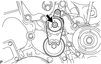
2. REMOVE V-RIBBED BELT TENSIONER ASSEMBLY
| (a) Remove the bolt and V-ribbed belt tensioner assembly. |
|
3. REMOVE COMPRESSOR ASSEMBLY WITH MOTOR
Click here .gif)
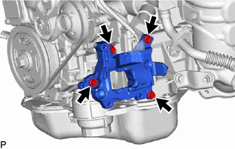
4. REMOVE NO. 1 COMPRESSOR MOUNTING BRACKET
| (a) Remove the 4 bolts and No. 1 compressor mounting bracket. |
|
5. REMOVE NO. 1 EXHAUST MANIFOLD HEAT INSULATOR
Click here
6. REMOVE NO. 2 EGR PIPE
Click here
7. REMOVE NO. 2 MANIFOLD STAY
Click here
8. REMOVE MANIFOLD STAY
Click here
9. REMOVE EXHAUST MANIFOLD CONVERTER SUB-ASSEMBLY
Click here
10. REMOVE THROTTLE WITH MOTOR BODY ASSEMBLY
Click here
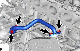
11. REMOVE WATER BY-PASS PIPE
| (a) Remove the 4 bolts, water by-pass pipe and 2 gaskets. |
|
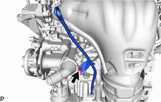
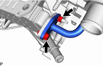
12. REMOVE EGR COOLER ASSEMBLY
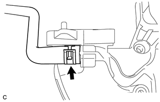
| (a) Slide the hose clamp and disconnect the No. 5 water by-pass hose from the EGR cooler assembly. |
|
.png)
| (b) Remove the bolt and nut, and disconnect the No. 1 EGR pipe from the EGR cooler assembly. |
|
| (c) Remove the bolt, nut and EGR cooler assembly. |
|
.png)
(d) Remove the gasket from the No. 1 EGR pipe.
13. REMOVE EGR VALVE ASSEMBLY
Click here
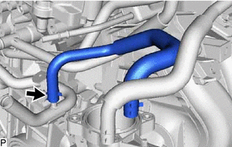
14. REMOVE NO. 3 WATER BY-PASS HOSE
| (a) Slide the hose clamp and remove the No. 3 water by-pass hose. |
|
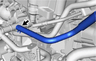
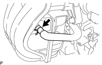
15. REMOVE NO. 1 WATER BY-PASS HOSE
| (a) Slide the hose clamp and remove the No. 1 water by-pass hose from the cylinder block. |
|
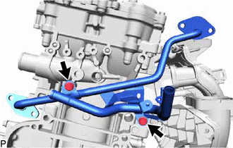
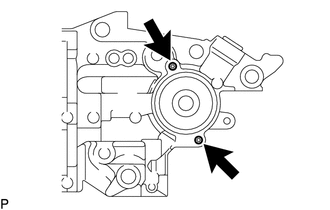
16. REMOVE NO. 1 EGR PIPE
| (a) Remove the 2 bolts and No. 1 EGR pipe. |
|
17. REMOVE ENGINE WATER PUMP ASSEMBLY
Click here
18. REMOVE WATER INLET
Click here
19. REMOVE THERMOSTAT
Click here
20. REMOVE OIL COOLER ASSEMBLY
Click here
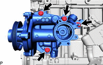
21. REMOVE WATER INLET HOUSING
| (a) Remove the 3 bolts, nut and water inlet housing from the cylinder block. |
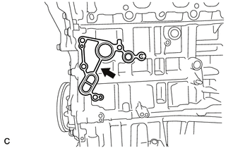
|
| (b) Remove the gasket. |
|
| (c) Using an E6 "TORX" socket wrench, remove the 2 stud bolts from the water inlet housing. NOTICE: If a stud bolt is deformed or its thread is damaged, replace it. |
|
22. REMOVE INTAKE MANIFOLD
| (a) Slide the clamp and disconnect the No. 2 PCV hose from the intake manifold. |
|
| (b) Slide the clamp and disconnect the purge line hose from the intake manifold. |
|
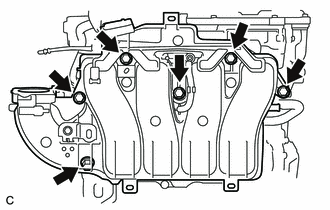
| (c) Remove the 6 bolts and intake manifold. |
|
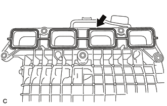
| (d) Remove the No. 1 intake manifold to head gasket from the intake manifold. |
|
23. REMOVE FUEL DELIVERY PIPE
Click here
24. REMOVE INJECTOR VIBRATION INSULATOR
Click here
25. REMOVE SENSOR WIRE
| (a) Disconnect the knock control sensor connector. |
|
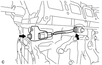
(b) Remove the bolt and sensor wire.
26. REMOVE IGNITION COIL ASSEMBLY
Click here
READ NEXT:
 Disassembly
DISASSEMBLY PROCEDURE 1. REMOVE ENGINE COVER JOINT (a) Remove the 3 engine cover joints. 2. REMOVE SPARK PLUG Click here 3. REMOVE KNOCK CONTROL SENSOR Click here 4. REMOVE ENGINE C
Inspection
INSPECTION PROCEDURE 1. INSPECT NO. 1 VALVE ROCKER ARM SUB-ASSEMBLY (a) Turn the roller by hand and check that it turns smoothly. If the roller does not turn smoothly, replace the No. 1 valve rocker a
Reassembly
REASSEMBLY PROCEDURE 1. INSTALL STIFFENING CRANKCASE RING PIN NOTICE: It is not necessary to remove the ring pin unless it is being replaced. *a Protrusion Height (a) Using a plastic-faced ha
SEE MORE:
Installation
INSTALLATION PROCEDURE 1. INSTALL RADIO SETTING CONDENSER (a) Attach the claw to install a new terminal cover to the wire harness. NOTICE:
Make sure to hold the crimping side of the terminal when installing the wire harness to the terminal cover.
Make sure not to bend the exposed wire when
Entry Interior Alarm does not Sound
DESCRIPTION The smart access system with push-button start (for Entry Function) uses the buzzer in the combination meter assembly (meter ECU) to perform various vehicle interior warnings. When the conditions of each warning are met, the certification ECU (smart key ECU assembly) sends a buzzer activ
