Lexus NX: Manifold Absolute Pressure Sensor
Components
COMPONENTS
ILLUSTRATION
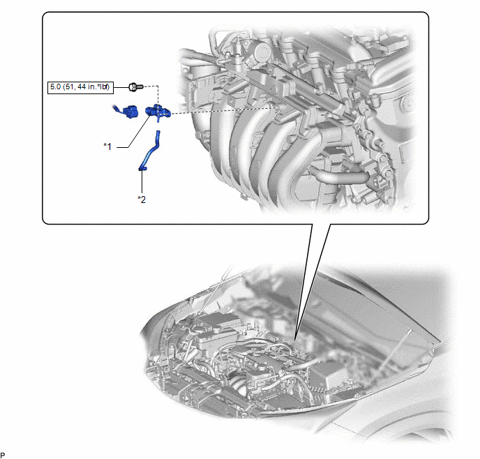
| *1 | MANIFOLD ABSOLUTE PRESSURE SENSOR | *2 | VACUUM HOSE |
.png) | N*m (kgf*cm, ft.*lbf): Specified torque | - | - |
On-vehicle Inspection
ON-VEHICLE INSPECTION
PROCEDURE
1. CHECK MANIFOLD ABSOLUTE PRESSURE SENSOR FUNCTION
(a) Connect the Techstream to the DLC3.
(b) Turn the power switch on (IG).
(c) Turn the Techstream on.
(d) Enter the following menus: Powertrain / Engine and ECT / Data List / MAP.
Powertrain > Engine and ECT > Data List| Tester Display |
|---|
| MAP |
(e) Read the values displayed on the Techstream.
Standard Condition:
80 to 110 kPa (0.8 to 1.1 kgf/cm2, 12 to 16 psi)
(f) Using the vacuum pump, measure the manifold absolute pressure sensor when a pressure of 67 kPa (503 mmHg, 19.8 in.Hg) is applied to the manifold absolute pressure sensor.
Standard Condition:
23 to 38 kPa (173 to 285 mmHg, 6.79 to 11.2 in.Hg)
Removal
REMOVAL
PROCEDURE
1. REMOVE MANIFOLD ABSOLUTE PRESSURE SENSOR
| (a) Disconnect the manifold absolute pressure sensor connector. |
|
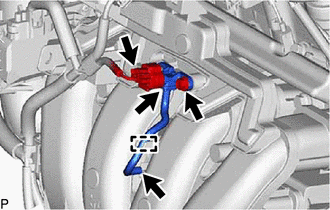
(b) Remove the clamp and disconnect the vacuum hose from the intake manifold.
(c) Remove the bolt and manifold absolute pressure sensor.
(d) Remove the manifold absolute pressure sensor from the vacuum hose.
Installation
INSTALLATION
PROCEDURE
1. INSTALL MANIFOLD ABSOLUTE PRESSURE SENSOR
(a) Install the manifold absolute pressure sensor to the vacuum hose.
(b) Install the manifold absolute pressure sensor with the bolt.
Torque:
5.0 N·m {51 kgf·cm, 44 in·lbf}
(c) Connect the clamp and vacuum hose to the intake manifold.
(d) Connect the manifold absolute pressure sensor connector.
READ NEXT:
 Mass Air Flow Meter
ComponentsCOMPONENTS ILLUSTRATION *1 MASS AIR FLOW METER SUB-ASSEMBLY - - On-vehicle InspectionON-VEHICLE INSPECTION CAUTION / NOTICE / HINT NOTICE:
Perform the mass air flow meter s
Relay
On-vehicle InspectionON-VEHICLE INSPECTION PROCEDURE 1. INSPECT JUNCTION BLOCK *1 Main Body ECU - - *a Component without harness connected (Junction Block) *b Component without ma
SEE MORE:
Components
COMPONENTS ILLUSTRATION *1 DECK FLOOR BOX LH *2 NO. 3 DECK BOARD SUB-ASSEMBLY *3 REAR DECK FLOOR BOX *4 NEGATIVE AUXILIARY BATTERY TERMINAL N*m (kgf*cm, ft.*lbf): Specified torque - - ILLUSTRATION *1 FRONT FLEXIBLE HOSE *2 UNON BOLT *3 GASKET - -
Data List / Active Test
DATA LIST / ACTIVE TEST READ DATA LIST NOTICE: In the table below, the values listed under "Normal Condition" are reference values. Do not depend solely on these reference values when deciding whether a part is faulty or not. HINT: Using the Techstream to read the Data List allows values or states o
