Lexus NX: Hybrid Battery System Discharge Time Too Long (P0C76-523)
DTC SUMMARY
MALFUNCTION DESCRIPTION
The hybrid vehicle control ECU detects that the electrical charge stored in the high-voltage condenser of the inverter with converter assembly cannot be discharged.
The cause of this malfunction may be one of the following:
- Voltage sensor (VH) malfunction
- Motor generator control ECU (MG ECU) malfunction
- Communication (wire harness) malfunction
- Inverter with converter assembly malfunction
- Hybrid vehicle control ECU malfunction
- Wire harness malfunction
- Inverter with converter assembly malfunction
DESCRIPTION
For a description of the inverter.
Click here .gif)
| DTC No. | Detection Item | DTC Detection Condition | Trouble Area | MIL | Warning Indicate |
|---|---|---|---|---|---|
| P0C76-523 | Hybrid Battery System Discharge Time Too Long | The inverter voltage (VH) does not drop during discharge. (Discharge: Offsetting of the residual pressure in the high-voltage side after power switch is turned off) (1 trip detection logic) |
| Does not come on | Master Warning Light: Comes on |
HINT:
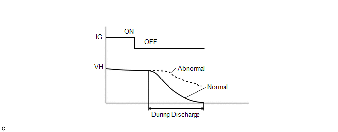
When the power switch is turned from on (READY) to off, the MG ECU discharges voltage stored in the inverter by allowing current to flow to motor (MG2) without generating torque. When the vehicle is normal, VH voltage becomes approximately 0 V after discharging. If VH voltage exceeds a specified value, this DTC is stored.
 Related Data List
 | DTC No. | Data List |
|---|---|
| P0C76-523 | VL-Voltage before Boosting |
The following items can be helpful when performing repairs:
- Ready Signal
WIRING DIAGRAM
Refer to the wiring diagram for the shut down signal circuit.
Click here
CAUTION / NOTICE / HINT
CAUTION:
- Before inspecting the high-voltage system or disconnecting the low voltage connector of the inverter with converter assembly, take safety precautions such as wearing insulated gloves and removing the service plug grip to prevent electrical shocks. After removing the service plug grip, put it in your pocket to prevent other technicians from accidentally reconnecting it while you are working on the high-voltage system.
-
After removing the service plug grip, wait for at least 10 minutes before touching any of the high-voltage connectors or terminals. After waiting for 10 minutes, check the voltage at the terminals in the inspection point in the inverter with converter assembly. The voltage should be 0 V before beginning work.
Click here
HINT:
Waiting for at least 10 minutes is required to discharge the high-voltage capacitor inside the inverter with converter assembly.
NOTICE:
After turning the power switch off, waiting time may be required before disconnecting the cable from the negative (-) auxiliary battery terminal. Therefore, make sure to read the disconnecting the cable from the negative (-) auxiliary battery terminal notices before proceeding with work.
Click here
HINT:
After the repair, clear the DTCs and perform the following procedure to check that DTCs are not output.
- Turn the power switch off and wait for 30 seconds or more.
- Turn the power switch on (READY) and wait for 30 seconds or more.
- Turn the power switch off and wait for 30 seconds or more.
PROCEDURE
| 1. | CHECK DTC OUTPUT (HYBRID CONTROL) |
(a) Connect the Techstream to the DLC3.
(b) Turn the power switch on (IG).
(c) Enter the following menus: Powertrain / Hybrid Control / Trouble Codes.
(d) Check for DTCs.
Powertrain > Hybrid Control > Trouble Codes| Result | Proceed to |
|---|---|
| P0C76-523 only is output, or DTCs except the ones in the table below are also output. | A |
| Any of the following DTCs including pending DTCs are also output. | B |
| Malfunction Content | Relevant DTC | |
|---|---|---|
| Microcomputer malfunction | P0A1A-151, 658, 791 | Generator Control Module |
| P0A1B-786 | Drive Motor "A" Control Module | |
| P0A1D-148 | Hybrid Powertrain Control Module | |
| P1C2A-155 | Generator A/D Converter Circuit | |
| P1CA6-156 | Generator Control Module Malfunction | |
| P1CA7-193 | Drive Motor Control Module Malfunction | |
| P1CAC-200 | Generator Position Sensor Angle Malfunction | |
| P1CAD-168 | Drive Motor "A" Position Sensor Angle Malfunction | |
| P1CAF-792 | Generator Position Sensor REF Signal Cycle Malfunction | |
| P1CB2-793 | Generator Position Sensor REF Signal Stop Malfunction | |
| P2511-149 | HV CPU Power Relay Sense Circuit Intermittent No Continuity | |
| P3133-659 | Communication Error from Generator to Drive Motor "A" | |
| P3134-661 | Communication Error from Drive Motor "A" to Generator | |
| P324E-788 | MG-ECU Power Relay Intermittent Circuit | |
| Power source circuit malfunction | P06B0-163 | Sensor Power Supply "A" Circuit / Open |
| P06D6-511 | Sensor Reference Voltage "F" Circuit / Open | |
| P06E6-164 | Sensor Power Supply "C" Circuit / Open | |
| P1C73-512 | Sensor Standard Voltage "F" Circuit / Open | |
| Communication system malfunction | U0110 (all INF codes)* | Lost Communication with Drive Motor Control Module "A" |
| Sensor and actuator circuit malfunction | P0A3F-243 | Drive Motor "A" Position Sensor Circuit |
| P0A40-500 | Drive Motor "A" Position Sensor Circuit Range / Performance | |
| P0A41-245 | Drive Motor "A" Position Sensor Circuit Low | |
| P0A4B-253 | Generator Position Sensor Circuit | |
| P0A4C-513 | Generator Position Sensor Circuit Range / Performance | |
| P0A4D-255 | Generator Position Sensor Circuit Low | |
| P0ADC-226 | Hybrid Battery Positive Contactor Control Circuit High | |
| P0AE0-228 | Hybrid Battery Negative Contactor Control Circuit High | |
| P0AE7-224 | Hybrid Battery Precharge Contactor Control Circuit High | |
| System malfunction | P0D2F-266 | Drive Motor "A" Inverter Voltage Sensor Circuit Low |
| P0D30-267 | Drive Motor "A" Inverter Voltage Sensor Circuit High | |
HINT:
- *1: If any INF codes are output for this DTC, refer to the corresponding diagnostic procedure.
-
P0C76-523 may be output as a result of the malfunction indicated by the DTCs above.
- The chart above is listed in inspection order of priority.
- Check DTCs that are output at the same time by following the listed order. (The main cause of the malfunction can be determined without performing unnecessary inspections.)
(e) Turn the power switch off.
| B | .gif) | GO TO DTC CHART (HYBRID CONTROL SYSTEM) |
|
.gif)
| 2. | CHECK SHUT DOWN SIGNAL CIRCUIT |
Click here
HINT:
If the "Shut Down Signal Circuit" inspection results are normal, perform the next step.
| NEXT | | REPLACE INVERTER WITH CONVERTER ASSEMBLY |
READ NEXT:
 DC/DC Converter Step Up Voltage Performance (P0CA3-442)
DTC SUMMARY MALFUNCTION DESCRIPTION This DTC indicates that it has been detected that the VH voltage cannot be boosted as commanded due to malfunction of the boost converter system. The cause of this
Drive Motor "A" Inverter Voltage Sensor Circuit Range / Performance (P0D2E-565)
DTC SUMMARY MALFUNCTION DESCRIPTION VH voltage sensor signal malfunction in the inverter for the motor. Internal inverter malfunction
Internal circuit malfunction in the inverter for the motor
Ma
Drive Motor "A" Inverter Voltage Sensor Circuit Low (P0D2F-266,P0D30-267)
DESCRIPTION The inverter contains a three-phase bridge circuit, which consists of 6 power transistors (IGBTs) each for the generator (MG1), motor (MG2) and rear motor (MGR). The inverter converts high
SEE MORE:
Fail-safe Chart
FAIL-SAFE CHART FAIL SAFE FUNCTION (a) The following chart shows the status of the controls when the system is normal and malfunctioning.
The passenger airbag ON/OFF indicator ("ON" and "OFF") comes on for approximately 4 seconds, and then goes off for approximately 2 seconds.
Approximately 6 s
Short in D Squib Circuit (B1800-B1803)
DESCRIPTION The driver side squib circuit consists of the airbag ECU assembly, spiral cable sub-assembly and horn button assembly. The circuit instructs the SRS to deploy when deployment conditions are met. These DTCs are stored when a malfunction is detected in the driver side squib circuit. DTC
