Lexus NX: On-vehicle Inspection
ON-VEHICLE INSPECTION
PROCEDURE
1. INSPECT WINDSHIELD WIPER MOTOR ASSEMBLY
(a) for LH Side:
| (1) Check the stop (park) position. |
|
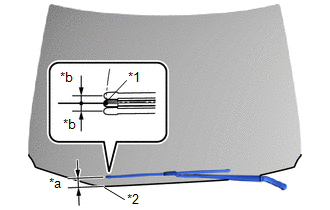
(2) Operate the windshield wiper motor assembly.
(3) Stop the windshield wiper motor assembly operation.
(4) Check the automatic stop (park) position.
HINT:
After the front wiper motor is stopped, check the automatic stop position after lifting the wiper blade 2 times.
OK:
The front wiper stops at the position shown in the illustration.
(b) for RH Side:
| (1) Check the stop (park) position. |
|
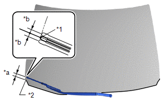
(2) Operate the windshield wiper motor assembly.
(3) Stop the windshield wiper motor assembly operation.
(4) Check the automatic stop (park) position.
HINT:
After the front wiper motor is stopped, check the automatic stop position after lifting the wiper blade 2 times.
OK:
The front wiper stops at the position shown in the illustration.
READ NEXT:
 Inspection
INSPECTION CAUTION / NOTICE / HINT CAUTION: Make sure that fingers or articles of clothing do not get caught in moving parts when performing this test. PROCEDURE 1. INSPECT WINDSHIELD WIPER MOTOR ASSE
Removal
REMOVAL PROCEDURE 1. REMOVE FRONT WIPER ARM HEAD CAP (a) Using a screwdriver, detach the 3 claws and remove the front wiper arm head cap. HINT:
Tape the screwdriver tip before use.
Use the sam
Installation
INSTALLATION PROCEDURE 1. INSTALL WINDSHIELD WIPER MOTOR ASSEMBLY (a) Install the windshield wiper motor assembly to the windshield wiper link assembly with the 3 bolts. Torque: 5.4 N·m {55 kgf·cm,
SEE MORE:
Components
COMPONENTS ILLUSTRATION *1 AIR FUEL RATIO SENSOR *2 INVERTER RESERVE TANK ASSEMBLY *3 NO. 1 EXHAUST MANIFOLD HEAT INSULATOR *4 WIRE HARNESS *5 RADIATOR HOSE CLAMP - - N*m (kgf*cm, ft.*lbf): Specified torque * For use with SST
System Description
SYSTEM DESCRIPTION GENERAL (a) This system uses ultrasonic sensors to detect any obstacles at the corners and the rear of the vehicle. The system then informs the driver of the distance between the sensors and an obstacle as well as their positions by indicating them on the multi-information display
