Lexus NX: On-vehicle Inspection
ON-VEHICLE INSPECTION
PROCEDURE
1. INSPECT RESERVOIR CAP
(a) Measure the valve opening pressure.
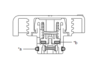
| *a | O-Ring |
| *b | Rubber Packing |
(1) If there are water stains or foreign matter on the O-ring, clean it with water and finger scouring.
(2) Check that the O-ring is not deformed, cracked or swollen.
(3) Apply engine coolant to the O-ring and rubber packing before using a radiator cap tester.
| (4) When using the radiator cap tester, tilt it more than 30° degrees. |
|
(5) Pump the radiator cap tester several times and check the maximum pressure*.
Pump speed:
1 pump per second
*: Even if the cap cannot maintain the maximum pressure, it is not a defect.
Standard Judgment Criterion:
| Item | Specified Condition |
|---|---|
| Standard value (for brand-new cap) | 93 to 123 kPa (1.0 to 1.3 kgf/cm2, 13.5 to 18 psi) |
| Minimum standard value (for used cap) | 79 kPa (0.8 kgf/cm2, 11.4 psi) |
If the maximum pressure is less than the minimum standard value, replace the reservoir cap.
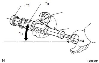
2. INSPECT FINS FOR BLOCKAGE
(a) If the fins are clogged, wash them with water or a steam cleaner and dry them with compressed air.
NOTICE:
- To avoid damaging the fins, the injection direction should be at right angles to the core surface.
-
If the steam cleaner is too close to the core, there is a possibility of damaging the fins, so maintain the following injection distances.
Standard Injection Distance:
Injection Pressure
Specified Condition
2942 to 4903 kPa (30.0 to 50.0 kgf/cm2, 427 to 711 psi)
300 mm (11.8 in.)
4903 to 7845 kPa (50.0 to 80.0 kgf/cm2, 711 to 1138 psi)
500 mm (19.7 in.)
- If the fins are bent, straighten them with a screwdriver or pliers.
- Do not expose electronic components to water.
(b) Dry the fins with compressed air.
READ NEXT:
 Removal
REMOVAL PROCEDURE 1. DRAIN ENGINE COOLANT Click here 2. REMOVE FRONT BUMPER REINFORCEMENT SUB-ASSEMBLY Click here 3. DISCONNECT HOOD LOCK ASSEMBLY (a) Detach the 2 clamps and disconnect the ho
Installation
INSTALLATION PROCEDURE 1. INSTALL LOWER RADIATOR SUPPORT (a) Install the 2 lower radiator supports to the fan shroud. 2. INSTALL RADIATOR SUPPORT CUSHION (a) Install the 2 radiator support cushions to
Relay
On-vehicle InspectionON-VEHICLE INSPECTION PROCEDURE 1. INSPECT COOLING FAN RELAY (FAN NO. 1) (a) Measure the resistance according to the value(s) in the table below. Standard Resistance: Test
SEE MORE:
Diagnosis System
DIAGNOSIS SYSTEM CHECK DLC3 (a) Check the DLC3. Click here INSPECT AUXILIARY BATTERY VOLTAGE (a) Measure the auxiliary battery voltage. Standard voltage: 11 to 14 V (power switch off) If the voltage is below 11 V, recharge or replace the auxiliary battery.
Components
COMPONENTS ILLUSTRATION *A w/o AVS - - *1 FRONT FLEXIBLE HOSE *2 FRONT SHOCK ABSORBER WITH COIL SPRING *3 FRONT SPEED SENSOR LH *4 FRONT STABILIZER LINK ASSEMBLY LH *5 FRONT SUSPENSION SUPPORT DUST COVER LH *6 FRONT SUSPENSION SUPPORT PLATE LH *7 COWL BO
