Lexus NX: Parts Location
Lexus NX Service Manual / Engine & Hybrid System / 2ar-fxe (engine Control) / Sfi System / Parts Location
PARTS LOCATION
ILLUSTRATION
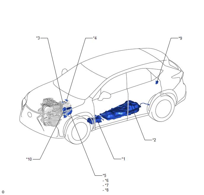
| *1 | CANISTER | *2 | FUEL PUMP |
| *3 | MASS AIR FLOW METER SUB-ASSEMBLY | *4 | PURGE VSV |
| *5 | NO. 1 ENGINE ROOM RELAY BLOCK AND JUNCTION BLOCK ASSEMBLY | *6 | EFI-MAIN RELAY |
| *7 | IG2-MAIN RELAY | *8 | EFI-MAIN NO. 2 RELAY |
| *9 | FUEL PUMP CONTROL ECU ASSEMBLY | *10 | ECM |
ILLUSTRATION
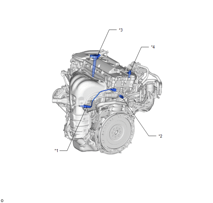
| *1 | AIR FUEL RATIO SENSOR | *2 | ENGINE COOLANT TEMPERATURE SENSOR |
| *3 | IGNITION COIL ASSEMBLY | *4 | CAMSHAFT POSITION SENSOR |
ILLUSTRATION
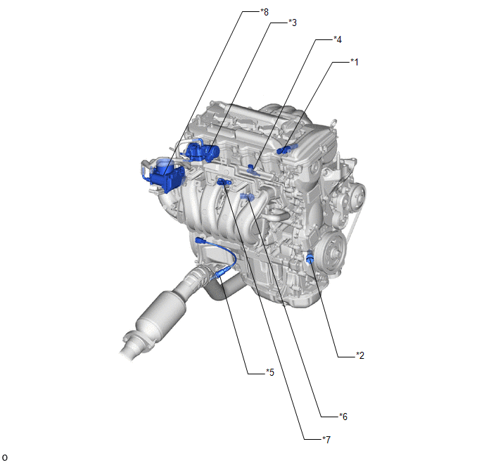
| *1 | CAMSHAFT TIMING OIL CONTROL VALVE ASSEMBLY | *2 | CRANKSHAFT POSITION SENSOR |
| *3 | EGR VALVE ASSEMBLY | *4 | FUEL INJECTOR ASSEMBLY |
| *5 | HEATED OXYGEN SENSOR | *6 | KNOCK CONTROL SENSOR |
| *7 | MANIFOLD ABSOLUTE PRESSURE SENSOR | *8 | THROTTLE BODY WITH MOTOR ASSEMBLY |
ILLUSTRATION
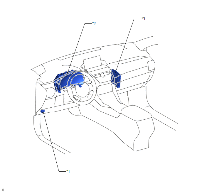
| *1 | DLC3 | *2 | COMBINATION METER ASSEMBLY |
| *3 | HYBRID VEHICLE CONTROL ECU | - | - |
READ NEXT:
 System Diagram
SYSTEM DIAGRAM
How To Proceed With Troubleshooting
CAUTION / NOTICE / HINT HINT: *: Use the Techstream. PROCEDURE 1. VEHICLE BROUGHT TO WORKSHOP
NEXT 2. CUSTOMER PROBLEM ANALYSIS
NEXT 3. CONNEC
Check For Intermittent Problems
CHECK FOR INTERMITTENT PROBLEMS HINT: Inspect the vehicle ECM using check mode. Intermittent problems are easier to detect with the Techstream when the ECM is in check mode. In check mode, the ECM use
SEE MORE:
Removal
REMOVAL PROCEDURE 1. REMOVE CONSOLE ARMREST ASSEMBLY Click here 2. REMOVE REAR UPPER CONSOLE PANEL Click here 3. REMOVE UPPER NO. 2 CONSOLE PANEL GARNISH Click here 4. REMOVE UPPER NO. 1 CONSOLE PANEL GARNISH Click here 5. REMOVE INSTRUMENT SIDE PANEL LH Click here 6. REMOVE NO.
Removal
REMOVAL CAUTION / NOTICE / HINT HINT:
Use the same procedure for the RH and LH sides.
The procedure listed below is for the LH side.
PROCEDURE 1. REMOVE BACK DOOR CENTER GARNISH Click here 2. REMOVE BACK DOOR SIDE GARNISH LH Click here 3. REMOVE BACK DOOR SIDE GARNISH RH Click here
© 2016-2026 Copyright www.lexunx.com
