Lexus NX: Parts Location
Lexus NX Service Manual / Engine & Hybrid System / Cruise Control / Front Radar Sensor System / Parts Location
PARTS LOCATION
ILLUSTRATION
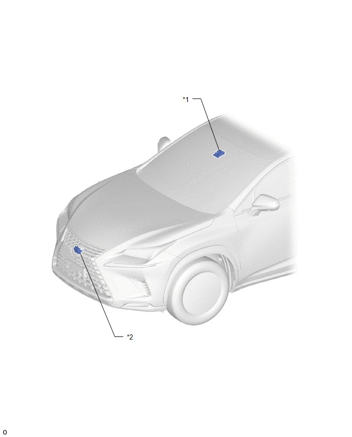
| *1 | FORWARD RECOGNITION CAMERA | *2 | MILLIMETER WAVE RADAR SENSOR ASSEMBLY |
ILLUSTRATION
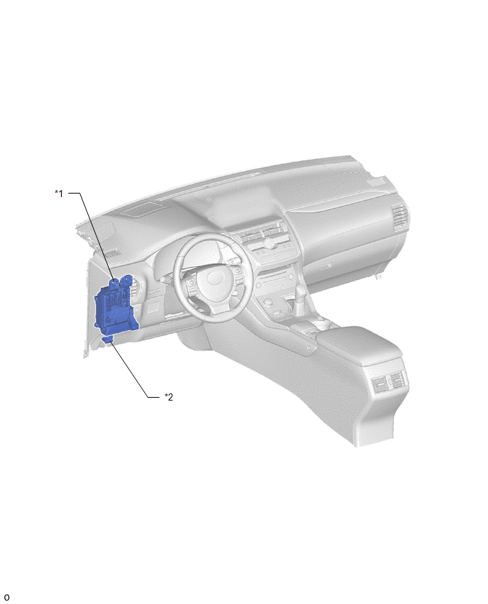
| *1 | INSTRUMENT PANEL JUNCTION BLOCK ASSEMBLY - ECU-IG NO.2 FUSE | *2 | DLC3 |
READ NEXT:
 System Diagram
SYSTEM DIAGRAM SYSTEM DIAGRAM LOCAL CAN CIRCUIT
How To Proceed With Troubleshooting
CAUTION / NOTICE / HINT HINT:
Before performing troubleshooting for the front radar sensor system, perform troubleshooting for the pre-collision system.
Click here
*: Use the Techstream.
PRO
Utility
UTILITY NOTICE:
When replacing the millimeter wave radar sensor assembly, always replace it with a new one. If a millimeter wave radar sensor assembly which was installed to another vehicle is used
SEE MORE:
Lost Communication With TCM (U0101,U0122,U0142,U0155,U0327,U1114,U1117)
DESCRIPTION These DTCs are stored when a malfunction occurs in the CAN communication circuit. DTC No. Detection Item Trouble Area U0101 Lost Communication With TCM
CAN communication system
ECM
Multiplex network door ECU
U0122 Lost Communication With Vehicle Dynamics Co
Removal
REMOVAL PROCEDURE 1. REMOVE CONSOLE BOX ASSEMBLY Click here 2. REMOVE DOOR SCUFF PLATE ASSEMBLY LH Click here 3. REMOVE COWL SIDE TRIM BOARD LH Click here 4. DISCONNECT FRONT FLOOR CARPET ASSEMBLY (a) Using a clip remover, remove the clip. *1 Hook *2 Fastener
© 2016-2026 Copyright www.lexunx.com
