Lexus NX: Pattern Select Switch Sport Mode Circuit
DESCRIPTION
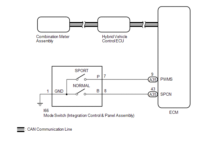
When selecting SPORT mode, the switch operation signal is sent to the ECM. Following this, the drive torque is optimally controlled to obtain a sporty feel in response to the driver's accelerator pedal operation.
WIRING DIAGRAM
PROCEDURE
| 1. | READ VALUE USING TECHSTREAM (CAN BUS CHECK) |
Click here .gif)
| Result | Proceed to |
|---|---|
| All of the ECUs and sensors that are currently connected to the CAN communication system are displayed. | A |
| None of the ECUs and sensors that are currently connected to the CAN communication system are displayed, or some of them are not displayed. | B |
| B | .gif) | GO TO CAN COMMUNICATION SYSTEM |
|
.gif)
| 2. | CHECK DTC OUTPUT (HEALTH CHECK) |
Click here
| DTCs are output. | | GO TO DTC CHART |
|
| 3. | READ VALUE USING TECHSTREAM (PATTERN SWITCH (PWR/M)) |
(a) Connect the Techstream to the DLC3.
(b) Turn the power switch on (IG).
(c) Enter the following menus: Powertrain / Hybrid Control / Data List / Pattern Switch (PWR/M).
Powertrain > Hybrid Control > Data List| Tester Display |
|---|
| Pattern Switch (PWR/M) |
(d) Read the value displayed on the Techstream.
Powertrain > Hybrid Control > Data List| Tester Display | Measurement Item | Range | Normal Condition |
|---|---|---|---|
| Pattern Switch (PWR/M) | SPORT mode transition availability | ON or OFF | In SPORT mode: ON Not in SPORT mode: OFF |
| Result | Proceed to |
|---|---|
| The Techstream display changes according to the mode switch (integration control & panel assembly) operation. | A |
| The Techstream display does not change according to the mode switch (integration control & panel assembly) operation. | B |
(e) Turn the power switch off.
| A | | CHECK FOR INTERMITTENT PROBLEMS |
|
| 4. | INSPECT INTEGRATION CONTROL & PANEL ASSEMBLY |
(a) Remove the integration control & panel assembly.
Click here
| (b) Measure the resistance according to the value(s) in the table below. Standard Resistance:
|
|
(c) Install the integration control & panel assembly.
| NG | | REPLACE INTEGRATION CONTROL & PANEL ASSEMBLY |
|
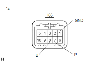
| 5. | CHECK HARNESS AND CONNECTOR (INTEGRATION CONTROL & PANEL ASSEMBLY - BODY GROUND) |
Click here
| NG | | REPAIR OR REPLACE HARNESS OR CONNECTOR |
|
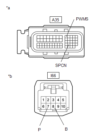
| 6. | CHECK HARNESS AND CONNECTOR (AIR CONDITIONING AMPLIFIER ASSEMBLY - ECO MODE SWITCH (INTEGRATION CONTROL & PANEL ASSEMBLY)) |
(a) Disconnect the A35 ECM connector.
(b) Disconnect the I66 integration control & panel assembly connector.
| (c) Measure the resistance according to the value(s) in the table below. Standard Resistance:
|
|
(d) Reconnect the I66 integration control & panel assembly connector.
(e) Reconnect the A35 ECM connector.
| OK | | REPLACE ECM |
| NG | | REPAIR OR REPLACE HARNESS OR CONNECTOR |
READ NEXT:
 Pattern Select Switch Eco Mode Circuit
DESCRIPTION When selecting ECO mode, the mode switch (integration control & panel assembly) operation signal is sent to the air conditioning amplifier assembly. Following this, ECO mode control is
Indicator Circuit
DESCRIPTION In accordance with the shift lever position, each shift position indicator light will turn on. WIRING DIAGRAM PROCEDURE 1. CHECK SHIFT POSITION INDICATOR (a) Turn the power switc
Drive Start Control System
DESCRIPTION The drive start control is controlled by the hybrid vehicle control ECU. If the hybrid vehicle control ECU determines that the shift lever and accelerator pedal are operated abnormally, dr
SEE MORE:
Installation
INSTALLATION CAUTION / NOTICE / HINT CAUTION: Wear protective gloves. Sharp areas on the parts may injure your hands. PROCEDURE 1. INSTALL BENCH TYPE REAR SEAT CUSHION COVER (REAR SEAT CUSHION HEATER) HINT:
When installing the seat cover, refer to the precautions in order to prevent wrinkles from
Removal
REMOVAL PROCEDURE 1. TABLE OF BOLT, SCREW AND CLIP HINT: All bolts, screws, and clips relevant to installing and removing the instrument panel are shown along with their alphabet code in the table below. 2. DISABLE AUTOAWAY/RETURN FUNCTION (for Power Tilt and Power Telescopic Steering Column) (a) D
