Lexus NX: Pattern Select Switch Eco Mode Circuit
DESCRIPTION
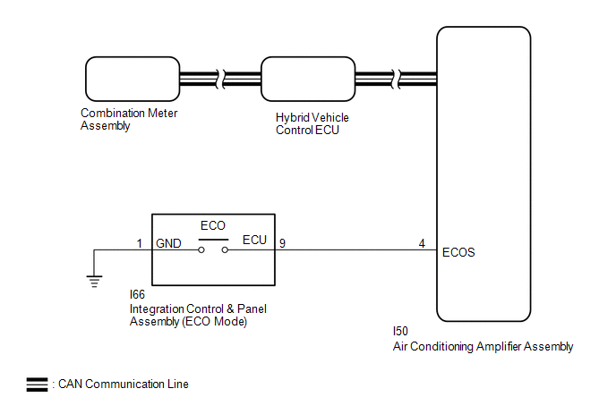
When selecting ECO mode, the mode switch (integration control & panel assembly) operation signal is sent to the air conditioning amplifier assembly. Following this, ECO mode control is activated for the heater and air conditioning system.
WIRING DIAGRAM
PROCEDURE
| 1. | READ VALUE USING TECHSTREAM (CAN BUS CHECK) |
Click here .gif)
| Result | Proceed to |
|---|---|
| All of the ECUs and sensors that are currently connected to the CAN communication system are displayed. | A |
| None of the ECUs and sensors that are currently connected to the CAN communication system are displayed, or some of them are not displayed. | B |
| B | .gif) | GO TO CAN COMMUNICATION SYSTEM |
|
.gif)
| 2. | CHECK DTC OUTPUT (HEALTH CHECK) |
Click here
| DTCs are output. | | GO TO DTC CHART |
|
| 3. | READ VALUE USING TECHSTREAM (ECO MODE) |
(a) Connect the Techstream to the DLC3.
(b) Turn the power switch on (IG).
(c) Enter the following menus: Powertrain / Hybrid Control / Data List / ECO Mode.
Powertrain > Hybrid Control > Data List| Tester Display |
|---|
| ECO Mode |
(d) Read the value displayed on the Techstream.
Powertrain > Hybrid Control > Data List| Tester Display | Measurement Item | Range | Normal Condition |
|---|---|---|---|
| ECO Mode | ECO mode transition availability | ON or OFF | In ECO mode: ON |
| Result | Proceed to |
|---|---|
| The Techstream display changes according to the integration control & panel assembly operation. | A |
| The Techstream display does not change according to the integration control & panel assembly operation. | B |
| A | | CHECK FOR INTERMITTENT PROBLEMS |
|
| 4. | READ VALUE USING TECHSTREAM (ECO SWITCH) |
(a) Connect the Techstream to the DLC3.
(b) Turn the power switch on (IG).
(c) Enter the following menus: Body Electrical / Air Conditioning / Data List / ECO Switch.
Body Electrical > Air Conditioner > Data List| Tester Display |
|---|
| ECO Switch |
(d) Read the value displayed on the Techstream.
Body Electrical > Air Conditioner > Data List| Tester Display | Measurement Item | Range | Normal Condition |
|---|---|---|---|
| ECO Switch | Integration control & panel assembly condition | ON or OFF | Integration control & panel assembly being turned and held at ECO position: ON Integration control & panel assembly not turned: OFF |
| Result | Proceed to |
|---|---|
| The Techstream display changes according to the integration control & panel assembly operation. | A |
| The Techstream display does not change according to the integration control & panel assembly operation. | B |
| A | | REPLACE AIR CONDITIONING AMPLIFIER ASSEMBLY |
|
| 5. | INSPECT INTEGRATION CONTROL & PANEL ASSEMBLY |
(a) Remove the integration control & panel assembly.
Click here
| (b) Measure the resistance according to the value(s) in the table below. Standard Resistance:
|
|
(c) Install the integration control & panel assembly.
| NG | | REPLACE INTEGRATION CONTROL & PANEL ASSEMBLY |
|
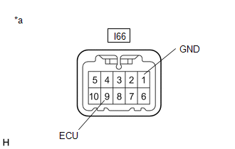
| 6. | CHECK HARNESS AND CONNECTOR (INTEGRATION CONTROL & PANEL ASSEMBLY - BODY GROUND) |
Click here
| NG | | REPAIR OR REPLACE HARNESS OR CONNECTOR |
|
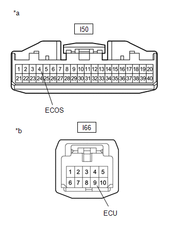
| 7. | CHECK HARNESS AND CONNECTOR (AIR CONDITIONING AMPLIFIER ASSEMBLY - INTEGRATION CONTROL & PANEL ASSEMBLY) |
(a) Disconnect the I50 air conditioning amplifier assembly connector.
Click here
(b) Disconnect the I66 integration control & panel assembly connector.
| (c) Measure the resistance according to the value(s) in the table below. Standard Resistance:
|
|
(d) Reconnect the I66 integration control & panel assembly connector.
(e) Reconnect the I50 air conditioning amplifier assembly connector.
| OK | | REPLACE AIR CONDITIONING AMPLIFIER ASSEMBLY |
| NG | | REPAIR OR REPLACE HARNESS OR CONNECTOR |
READ NEXT:
 Indicator Circuit
DESCRIPTION In accordance with the shift lever position, each shift position indicator light will turn on. WIRING DIAGRAM PROCEDURE 1. CHECK SHIFT POSITION INDICATOR (a) Turn the power switc
Drive Start Control System
DESCRIPTION The drive start control is controlled by the hybrid vehicle control ECU. If the hybrid vehicle control ECU determines that the shift lever and accelerator pedal are operated abnormally, dr
ECU Power Source Circuit
DESCRIPTION If the power switch is on (IG), the hybrid vehicle control ECU applies current to the MREL terminal to turn the IGCT relay on. This supplies power to the +B1 and +B2 terminals. WIRING DIAG
SEE MORE:
Terminals Of Ecu
TERMINALS OF ECU NOTICE:
After turning the power switch off, waiting time may be required before disconnecting the cable from the negative (-) auxiliary battery terminal.
Click here
When disconnecting and reconnecting the auxiliary battery.
Click here HINT: When disconnecting and reconnecti
Removal
REMOVAL CAUTION / NOTICE / HINT HINT:
Use the same procedure for the RH and LH sides.
The procedure listed below is for the LH side.
PROCEDURE 1. PRECAUTION NOTICE: After the power switch is turned off, there may be a waiting time before disconnecting the negative (-) auxiliary battery termi
