Lexus NX: Power Point Socket(for Console Box)
Components
COMPONENTS
ILLUSTRATION
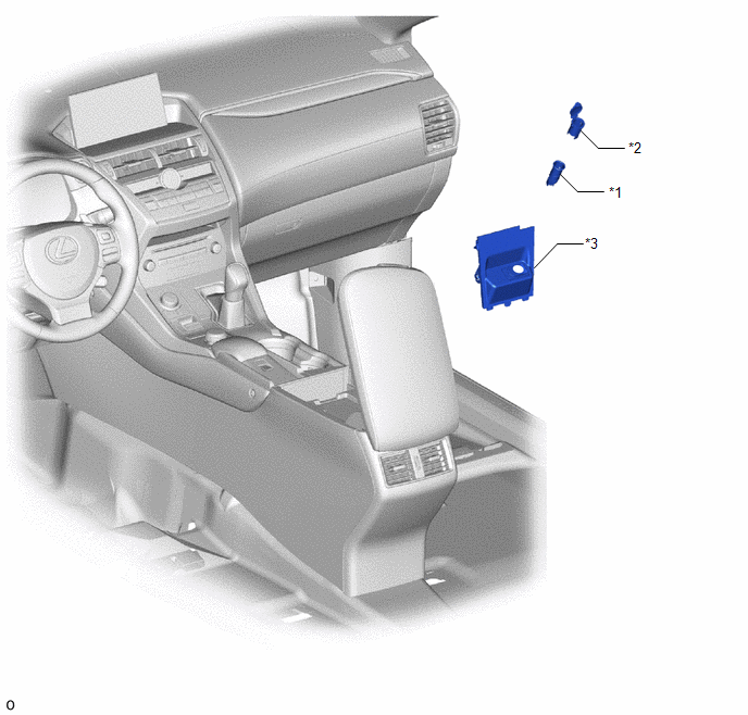
| *1 | NO. 1 POWER OUTLET SOCKET ASSEMBLY | *2 | NO. 1 POWER OUTLET SOCKET COVER |
| *3 | NO. 3 BOX PANEL | - | - |
Removal
REMOVAL
PROCEDURE
1. REMOVE NO. 3 BOX PANEL
Click here .gif)
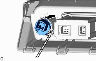
2. REMOVE NO. 1 POWER OUTLET SOCKET ASSEMBLY
(a) Using a thin-bladed screwdriver, detach the claw and remove the No. 1 power outlet socket assembly.
.png) | Protective Tape |
HINT:
Tape the thin-bladed screwdriver tip before use.
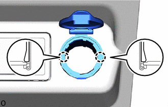
3. REMOVE NO. 1 POWER OUTLET SOCKET COVER
| (a) Detach the 2 claws and remove the No. 1 power outlet socket cover. |
|
Installation
INSTALLATION
PROCEDURE
1. INSTALL NO. 1 POWER OUTLET SOCKET COVER
| (a) Attach the 2 claws to install the No. 1 power outlet socket cover. |
|
.png)
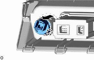
2. INSTALL NO. 1 POWER OUTLET SOCKET ASSEMBLY
| (a) Attach the claw to install the No. 1 power outlet socket assembly. |
|
3. INSTALL NO. 3 BOX PANEL
Click here .gif)
READ NEXT:
 Relay
Relay
On-vehicle InspectionON-VEHICLE INSPECTION PROCEDURE 1. INSPECT POWER OUTLET SOCKET RELAY (a) Remove the power outlet socket relay. (b) Measure the resistance according to the value(s)
Voltage Inverter
ComponentsCOMPONENTS ILLUSTRATION *1 DECK BOARD ASSEMBLY *2 DECK FLOOR BOX LH *3 NO. 2 DECK BOARD SUB-ASSEMBLY *4 NO. 3 DECK BOARD SUB-ASSEMBLY *5 REAR DECK FLOOR BOX -
Wireless Charger Assembly
ComponentsCOMPONENTS ILLUSTRATION *1 MOBILE WIRELESS CHARGER CRADLE ASSEMBLY - - RemovalREMOVAL PROCEDURE 1. REMOVE MOBILE WIRELESS CHARGER CRADLE ASSEMBLY (a) Remove the 5 screws.
SEE MORE:
DC/DC Converter Step Up Voltage Performance (P0CA3-442)
DTC SUMMARY MALFUNCTION DESCRIPTION This DTC indicates that it has been detected that the VH voltage cannot be boosted as commanded due to malfunction of the boost converter system. The cause of this malfunction may be one of the following: Internal inverter malfunction
Inverter with converter as
Installation
INSTALLATION CAUTION / NOTICE / HINT PROCEDURE 1. INSTALL QUARTER OUTSIDE MOULDING SUB-ASSEMBLY LH HINT: When installing the quarter outside moulding sub-assembly LH, heat the vehicle body and quarter outside moulding sub-assembly LH using a heat light. Standard: Item Temperature Vehicle B
