Lexus NX: Power Seat Power Easy Access System Function does not Operate
DESCRIPTION
-
The seat slides backward when either of the following conditions is met:
- The driver seat belt is unfastened with the power switch off and the shift lever in P.
- The power switch is turned from on (IG) or on (ACC) to off with the shift lever in P or N and the driver seat belt unfastened.
-
The seat slides forward when either of the following conditions is met:
- The driver seat belt is fastened with the power switch on (IG) or on (ACC) and the shift lever in P or N.
- The power switch is turned from off to on (IG) or on (ACC) with the shift lever in P or N and the driver seat belt unfastened.
WIRING DIAGRAM
CAUTION / NOTICE / HINT
NOTICE:
-
The front power seat control system (w/ Memory) uses the CAN communication system. First, confirm that there is no malfunction in the CAN communication system. Refer to the How to Proceed with Troubleshooting procedure.
Click here
.gif)
- Inspect the fuses for circuits related to this system before performing the following procedure.
HINT:
When troubleshooting a function, first make sure that the function is set to the default setting.
Click here
PROCEDURE
| 1. | CHECK FRONT POWER SEAT OPERATION |
(a) Check that each function of the power seat operates normally by using the front power seat switch LH.
Click here
| NG | .gif) | GO TO OTHER DIAGNOSTIC PROCEDURE (Front Power Seat does not Operate with Front Power Seat Switch) |
|
.gif)
| 2. | CHECK SEAT POSITION MEMORY FUNCTION |
(a) Check that the seat position memory function.
Click here
OK:
Seat position memory function is normal.
| NG | | GO TO OTHER DIAGNOSTIC PROCEDURE (Power Seat does not Return to Memorized Position) |
|
| 3. | READ VALUE USING TECHSTREAM (DRIVER SEAT BUCKLE SW) |
(a) Connect the Techstream to the DLC3.
(b) Turn the power switch on (IG).
(c) Turn the Techstream on.
(d) Enter the following menus: Body Electrical / Driver Seat / Data List.
(e) Read the Data List according to the display on the Techstream.
Body Electrical > Driver Seat > Data List| Tester Display | Measurement Item | Range | Normal Condition | Diagnostic Note |
|---|---|---|---|---|
| Driver Seat Buckle SW | Driver seat belt buckle switch | ON or OFF | ON: Driver seat belt fastened OFF: Driver seat belt unfastened | - |
| Tester Display |
|---|
| Driver Seat Buckle SW |
OK:
On the Techstream screen, the item changes between ON and OFF according to the above.
| NG | | GO TO STEP 6 |
|
| 4. | INSPECT FRONT SEAT OUTER BELT ASSEMBLY LH |
(a) Remove the front seat outer belt assembly LH.
Click here
(b) Inspect the front seat outer belt assembly LH.
Click here
| NG | | REPLACE FRONT SEAT OUTER BELT ASSEMBLY LH |
|
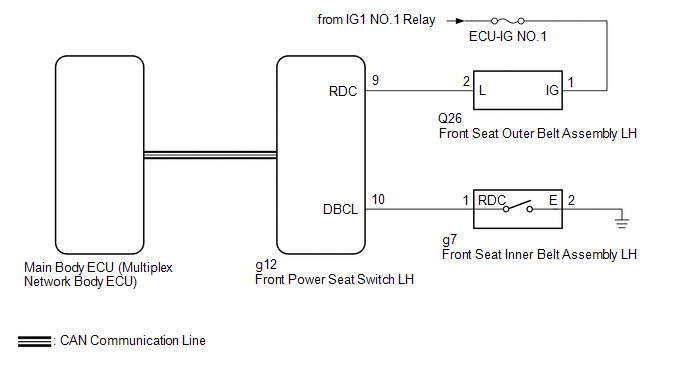
| 5. | CHECK HARNESS AND CONNECTOR (FRONT SEAT OUTER BELT ASSEMBLY LH - FRONT POWER SEAT SWITCH LH AND BATTERY) |
(a) Disconnect the Q26 front seat outer belt assembly LH connector.
(b) Disconnect the g12 front power seat switch LH connector.
(c) Measure the resistance according to the value(s) in the table below.
Standard Resistance:
| Tester Connection | Condition | Specified Condition |
|---|---|---|
| Q26-2 (L) - g12-9 (RDC) | Always | Below 1 Ω |
| Q26-2 (L) or g12-9 (RDC) - Body ground | Always | 10 kΩ or higher |
(d) Measure the voltage according to the value(s) in the table below.
Standard Voltage:
| Tester Connection | Switch Condition | Specified Condition |
|---|---|---|
| Q26-1 (IG) - Body ground | Power switch on (IG) | 11 to 14 V |
| Q26-1 (IG) - Body ground | Power switch off | Below 1 V |
| OK | | REPLACE FRONT POWER SEAT SWITCH LH |
| NG | | REPAIR OR REPLACE HARNESS OR CONNECTOR |
| 6. | INSPECT FRONT SEAT INNER BELT ASSEMBLY LH |
(a) Remove the front seat inner belt assembly LH.
Click here
(b) Inspect the front seat inner belt assembly LH.
Click here
| NG | | REPLACE FRONT SEAT INNER BELT ASSEMBLY LH |
|
| 7. | CHECK HARNESS AND CONNECTOR (FRONT POWER SEAT SWITCH LH - FRONT SEAT INNER BELT ASSEMBLY LH AND BODY GROUND) |
(a) Disconnect the g12 front power seat switch LH connector.
(b) Disconnect the g7 front seat inner belt assembly LH connector.
(c) Measure the resistance according to the value(s) in the table below.
Standard Resistance:
| Tester Connection | Condition | Specified Condition |
|---|---|---|
| g12-10 (DBCL) - g7-1 (RDC) | Always | Below 1 Ω |
| g12-10 (DBCL) or g7-1 (RDC) - Body ground | Always | 10 kΩ or higher |
| OK | | REPLACE FRONT POWER SEAT SWITCH LH |
| NG | | REPAIR OR REPLACE HARNESS OR CONNECTOR |
READ NEXT:
 Parts Location
PARTS LOCATION ILLUSTRATION *1 NO. 2 ENGINE ROOM RELAY BLOCK
- P/SEAT F/R FUSE
*2 INSTRUMENT PANEL JUNCTION BLOCK ASSEMBLY
- P/SEAT F/L FUSE
ILLUSTRATION *A for Driver S
System Diagram
SYSTEM DIAGRAM
SEE MORE:
GSW Terminal Circuit Malfunction (B1243)
DESCRIPTION If the collision door lock release function does not operate normally, or an open or short in the GSW input circuit of the main body ECU (multiplex network body ECU) is detected, DTC B1243 will be stored. DTC No. Detection Item DTC Detection Condition Trouble Area B1243 GS
Inspection
INSPECTION PROCEDURE 1. INSPECT TRIP SWITCH (LIGHT CONTROL RHEOSTAT) *1 Up Switch *2 Down Switch *a Component without harness connected (Trip Switch (Light Control Rheostat)) (a) Check the resistance. Measure the resistance according to the value(s) in the table below. Standard
