Lexus NX: Cornering Light Circuit
DESCRIPTION
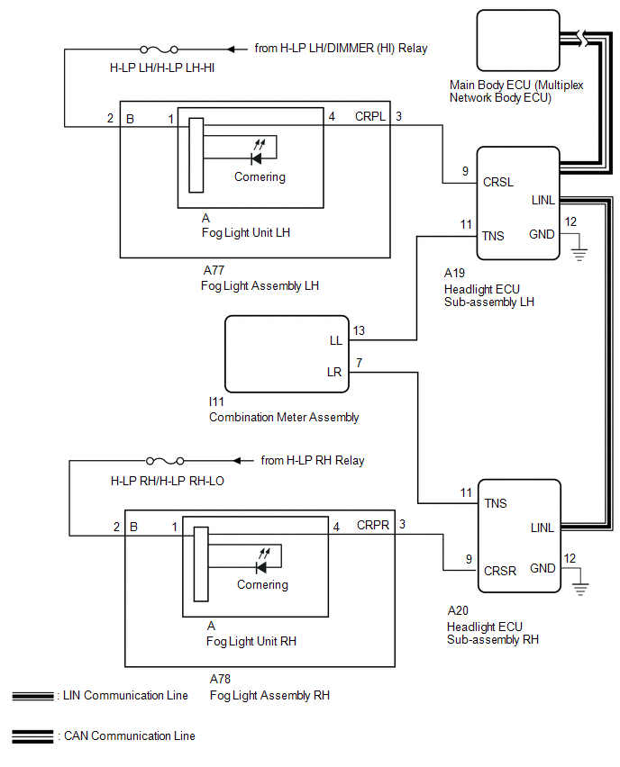
The illumination of the fog light assembly (cornering light) is controlled by the headlight ECU sub-assembly.
WIRING DIAGRAM
CAUTION / NOTICE / HINT
NOTICE:
-
The light system (for Triple Beam Headlight) uses the CAN communication system and multiplex communication system (LIN). First perform the communication function checks in "How to Proceed with Troubleshooting" to confirm that there are no communication malfunctions before proceeding with troubleshooting.
Click here
.gif)
-
After the headlight ECU sub-assembly LH is replaced, vehicle information registration and initialization are necessary.
Click here
-
Check that meter/gauge system DTCs B1507 and B1508 are not output.
Click here
- Check the fuses for circuits related to this system before performing the following inspection procedure.
PROCEDURE
| 1. | PERFORM ACTIVE TEST USING TECHSTREAM (CORNERING LIGHT) |
(a) Using the Techstream, perform the Active Test.
Click here
(1) for Single Beam Headlight:
Body Electrical > HL AutoLeveling > Active Test| Tester Display | Measurement Item | Control Range | Diagnostic Note |
|---|---|---|---|
| Cornering Light | Illuminates cornering lights | ON or OFF | - |
| Tester Display |
|---|
| Cornering Light |
(2) for Triple Beam Headlight:
Body Electrical > AFS > Active Test| Tester Display | Measurement Item | Control Range | Diagnostic Note |
|---|---|---|---|
| Cornering Light | Illuminates cornering lights | ON or OFF | - |
| Tester Display |
|---|
| Cornering Light |
| Result | Proceed to |
|---|---|
| The Active Test is performed normally | A |
| The Active Test is not performed normally for the right side light only | B |
| The Active Test is not performed normally for the left side light only | C |
| A | .gif) | PROCEED TO NEXT SUSPECTED AREA SHOWN IN PROBLEM SYMPTOMS TABLE |
| C | | GO TO STEP 6 |
|
.gif)
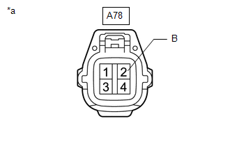
| 2. | CHECK HARNESS AND CONNECTOR (FOG LIGHT ASSEMBLY RH - BATTERY) |
| (a) Disconnect the fog light assembly RH connector. |
|
(b) Measure the voltage according to the value(s) in the table below.
Standard Voltage:
| Tester Connection | Switch Condition | Specified Condition |
|---|---|---|
| A78-2 (B) - Body ground | Power switch on (IG) | 11 to 14 V |
| NG | | REPAIR OR REPLACE HARNESS OR CONNECTOR |
|
| 3. | CHECK HARNESS AND CONNECTOR (HEADLIGHT ECU SUB-ASSEMBLY RH - FOG LIGHT ASSEMBLY RH) |
(a) Disconnect the A20 headlight ECU sub-assembly RH connector.
(b) Disconnect the A78 fog light assembly RH connector.
(c) Measure the resistance according to the value(s) in the table below.
Standard Resistance:
| Tester Connection | Condition | Specified Condition |
|---|---|---|
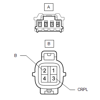
| A20-9 (CRSR) - A78-3 (CRPR) | Always | Below 1 Ω |
| A20-9 (CRSR) or A78-3 (CRPR) - Body ground | Always | 10 kΩ or higher |
| NG | | REPAIR OR REPLACE HARNESS OR CONNECTOR |
|
| 4. | INSPECT FOG LIGHT ASSEMBLY RH |
(a) Remove the fog light assembly RH.
Click here
(b) Inspect the fog light assembly RH.
Click here
| OK | | REPLACE HEADLIGHT ECU SUB-ASSEMBLY RH |
|
| 5. | INSPECT FOG LIGHT ASSEMBLY RH |
| (a) Remove the fog light assembly RH. Click here |
|
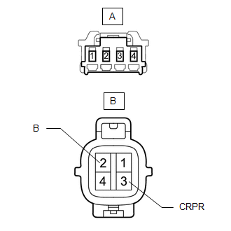
(b) Remove the fog light unit RH from the fog light assembly RH.
Click here
(c) Measure the resistance according to the value(s) in the table below.
Standard Resistance:
| Tester Connection | Condition | Specified Condition |
|---|---|---|
| A-1 - B-2 (B) | Always | Below 1 Ω |
| A-4 - B-3 (CRPR) | Always | 10 kΩ or higher |
| OK | | REPLACE FOG LIGHT UNIT RH |
| NG | | REPLACE FOG LIGHT ASSEMBLY RH |
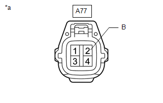
| 6. | CHECK HARNESS AND CONNECTOR (FOG LIGHT ASSEMBLY LH - BATTERY) |
| (a) Disconnect the fog light assembly LH connector. |
|
(b) Measure the voltage according to the value(s) in the table below.
Standard Voltage:
| Tester Connection | Switch Condition | Specified Condition |
|---|---|---|
| A77-2 (B) - Body ground | Power switch on (IG) | 11 to 14 V |
| NG | | REPAIR OR REPLACE HARNESS OR CONNECTOR |
|
| 7. | CHECK HARNESS AND CONNECTOR (HEADLIGHT ECU SUB-ASSEMBLY LH - FOG LIGHT ASSEMBLY LH) |
(a) Disconnect the A19 headlight ECU sub-assembly LH connector.
(b) Disconnect the A77 fog light assembly LH connector.
(c) Measure the resistance according to the value(s) in the table below.
Standard Resistance:
| Tester Connection | Condition | Specified Condition |
|---|---|---|
| A19-9 (CRSL) - A77-3 (CRPL) | Always | Below 1 Ω |
| A19-9 (CRSL) or A77-3 (CRPL) - Body ground | Always | 10 kΩ or higher |
| NG | | REPAIR OR REPLACE HARNESS OR CONNECTOR |
|
| 8. | INSPECT FOG LIGHT ASSEMBLY LH |
(a) Remove the fog light assembly LH.
Click here
(b) Inspect the fog light assembly LH.
Click here
| OK | | REPLACE HEADLIGHT ECU SUB-ASSEMBLY LH |
|
| 9. | INSPECT FOG LIGHT ASSEMBLY LH |
| (a) Remove the fog light assembly LH. Click here |
|
(b) Remove the fog light unit LH from the fog light assembly LH.
Click here
(c) Measure the resistance according to the value(s) in the table below.
Standard Resistance:
| Tester Connection | Condition | Specified Condition |
|---|---|---|
| A-1 - B-2 (B) | Always | Below 1 Ω |
| A-4 - B-3 (CRPL) | Always | 10 kΩ or higher |
| OK | | REPLACE FOG LIGHT UNIT LH |
| NG | | REPLACE FOG LIGHT ASSEMBLY LH |
READ NEXT:
 Precaution
PRECAUTION NOTICE: When disassembling the rear combination light assembly, use static electricity countermeasures SST (desktop antistatic mat set) and observe all precautions to prevent damage to the
Components
COMPONENTS ILLUSTRATION *1 TONNEAU COVER ASSEMBLY - - ILLUSTRATION *1 DECK BOARD ASSEMBLY *2 DECK FLOOR BOX LH *3 DECK FLOOR BOX RH *4 NO. 2 DECK BOARD SUB-ASSEMBLY
SEE MORE:
Parts Location
PARTS LOCATION ILLUSTRATION *1 FRONT ABSORBER CONTROL ACTUATOR RH (FRONT SHOCK ABSORBER ASSEMBLY RH) *2 FRONT ABSORBER CONTROL ACTUATOR LH (FRONT SHOCK ABSORBER ASSEMBLY LH) *3 REAR ABSORBER CONTROL ACTUATOR RH (REAR SHOCK ABSORBER ASSEMBLY RH) *4 REAR ABSORBER CONTROL ACTUATOR L
Image from Camera for Parking Assist Monitor is Abnormal
DESCRIPTION The video signal from the rear television camera assembly is transmitted to the multi-display assembly. WIRING DIAGRAM CAUTION / NOTICE / HINT NOTICE:
When the "!" mark is displayed on the multi-display assembly after disconnecting the cable from the negative (-) auxiliary battery te
