Lexus NX: Fold Seat Switch Circuit
DESCRIPTION
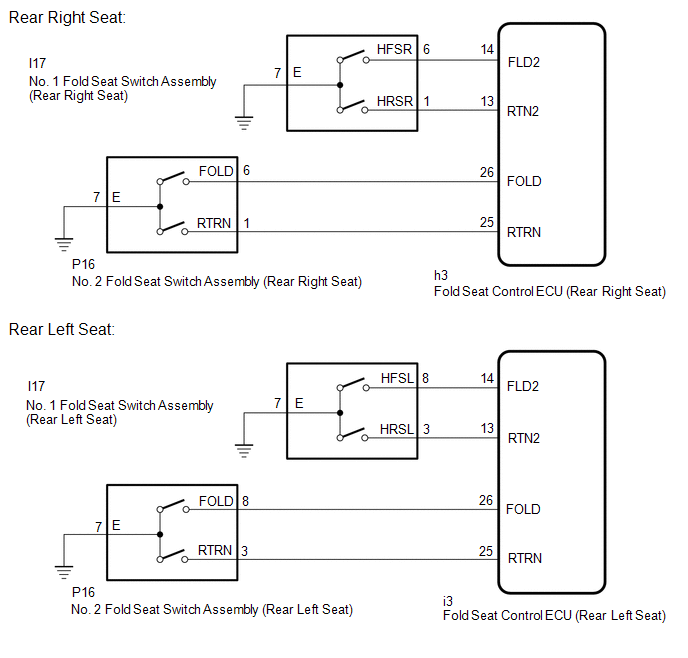
When the fold seat switch is operated, a switch operation signal is sent to the fold seat control ECU. The ECU receives switch operation signals from each switch and activates the reclining motor and cushion motor.
WIRING DIAGRAM
PROCEDURE
| 1. | CHECK FOLD SEAT CONTROL ECU (FOLD SEAT SWITCH SIGNAL) |
| (a) Check the No. 1 fold seat switch signal. (1) Remove the fold seat control ECU with its connectors still connected. Click here (2) Measure the voltage according to the value(s) in the table below. Standard Voltage: Rear Right Seat
|
|
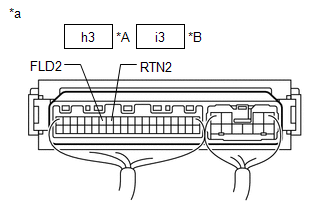
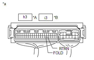
| (b) Check No. 2 fold seat switch signal. (1) Remove the fold seat control ECU with its connectors still connected. Click here (2) Measure the voltage according to the value(s) in the table below. Standard Voltage: Rear Right Seat
|
|
| A | .gif) | PROCEED TO NEXT SUSPECTED AREA SHOWN IN PROBLEM SYMPTOMS TABLE |
| C | | GO TO STEP 4 |
|
.gif)
| 2. | INSPECT NO. 1 FOLD SEAT SWITCH ASSEMBLY |
(a) Remove the No. 1 fold seat switch assembly.
Click here .gif)
(b) Inspect the No. 1 fold seat switch assembly.
Click here
| NG | | REPLACE NO. 1 FOLD SEAT SWITCH ASSEMBLY |
|
| 3. | CHECK HARNESS AND CONNECTOR (NO. 1 FOLD SEAT SWITCH ASSEMBLY - FOLD SEAT CONTROL ECU AND BODY GROUND) |
(a) Disconnect the I17 No. 1 fold seat switch assembly connector.
(b) Disconnect the h3*1 or i3*2 ECU connector.
- *1: Rear Right Seat
- *2: Rear Left Seat
(c) Measure the resistance according to the value(s) in the table below.
Standard Resistance:
Rear Right Seat| Tester Connection | Condition | Specified Condition |
|---|---|---|
| I17-6 (HFSR) - h3-14 (FLD2) | Always | Below 1 Ω |
| I17-6 (HFSR) or h3-14 (FLD2) - Body ground | Always | 10 kΩ or higher |
| I17-1 (HRSR) - h3-13 (RTN2) | Always | Below 1 Ω |
| I17-1 (HRSR) or h3-13 (RTN2) - Body ground | Always | 10 kΩ or higher |
| I17-7 (E) - Body ground | Always | Below 1 Ω |
| Tester Connection | Condition | Specified Condition |
|---|---|---|
| I17-8 (HFSL) - i3-14 (FLD2) | Always | Below 1 Ω |
| I17-8 (HFSL) or i3-14 (FLD2) - Body ground | Always | 10 kΩ or higher |
| I17-3 (HRSL) - i3-13 (RTN2) | Always | Below 1 Ω |
| I17-3 (HRSL) or i3-13 (RTN2) - Body ground | Always | 10 kΩ or higher |
| I17-7 (E) - Body ground | Always | Below 1 Ω |
| OK | | REPLACE FOLD SEAT CONTROL ECU |
| NG | | REPAIR OR REPLACE HARNESS OR CONNECTOR |
| 4. | INSPECT NO. 2 FOLD SEAT SWITCH ASSEMBLY |
(a) Remove the No. 2 fold seat switch assembly.
Click here
(b) Inspect the No. 2 fold seat switch assembly.
Click here
| NG | | REPLACE NO. 2 FOLD SEAT SWITCH ASSEMBLY |
|
| 5. | CHECK HARNESS AND CONNECTOR (NO. 2 FOLD SEAT SWITCH ASSEMBLY - FOLD SEAT CONTROL ECU AND BODY GROUND) |
(a) Disconnect the P16 No. 2 fold seat switch assembly connector.
(b) Disconnect the h3*1 or i3*2 fold seat control ECU connector.
- *1: Rear Right Seat
- *2: Rear Left Seat
(c) Measure the resistance according to the value(s) in the table below.
Standard Resistance:
Rear Right Seat| Tester Connection | Condition | Specified Condition |
|---|---|---|
| P16-6 (FOLD) - h3-26 (FOLD) | Always | Below 1 Ω |
| P16-6 (FOLD) or h3-26 (FOLD) - Body ground | Always | 10 kΩ or higher |
| P16-1 (RTRN) - h3-25 (RTRN) | Always | Below 1 Ω |
| P16-1 (RTRN) or h3-25 (RTRN) - Body ground | Always | 10 kΩ or higher |
| P16-7 (E) - Body ground | Always | Below 1 Ω |
| Tester Connection | Condition | Specified Condition |
|---|---|---|
| P16-8 (FOLD) - i3-26 (FOLD) | Always | Below 1 Ω |
| P16-8 (FOLD) or i3-26 (FOLD) - Body ground | Always | 10 kΩ or higher |
| P16-3 (RTRN) - i3-25 (RTRN) | Always | Below 1 Ω |
| P16-3 (RTRN) or i3-25 (RTRN) - Body ground | Always | 10 kΩ or higher |
| P16-7 (E) - Body ground | Always | Below 1 Ω |
| OK | | REPLACE FOLD SEAT CONTROL ECU |
| NG | | REPAIR OR REPLACE HARNESS OR CONNECTOR |
READ NEXT:
 Folding Motor Circuit
DESCRIPTION The fold seat control ECU receives switch operation signals from the No. 1 and No. 2 fold seat switches and activates the power seat motors. At this time, the Hall IC detects the actuation
Reclining Motor Circuit
DESCRIPTION The fold seat control ECU receives switch operation signals from the No. 1 and No. 2 fold seat switches and rear power seat switch and activates the power seat motors. At this time, the Ha
Rear Power Seat Switch Circuit
DESCRIPTION When the rear power seat switch is operated, a recline signal is sent to the fold seat control ECU. The ECU activates the power seat motor based on the signal from the rear power seat swit
SEE MORE:
Precaution
PRECAUTION INITIALIZATION NOTICE: Perform Registration (VIN registration) when replacing the ECM. Click here DISCONNECT CABLE FROM NEGATIVE AUXILIARY BATTERY TERMINAL NOTICE:
After the power switch is turned off, there may be a waiting time before disconnecting the negative (-) auxiliary batter
Installation
INSTALLATION PROCEDURE 1. INSTALL AIRBAG ECU ASSEMBLY (a) Check that the power switch is off. (b) Check that the cable is disconnected from the negative (-) auxiliary battery terminal. CAUTION: Wait at least 90 seconds after disconnecting the cable from the negative (-) auxiliary battery terminal to
