Lexus NX: Back Door Courtesy Switch Circuit
DESCRIPTION
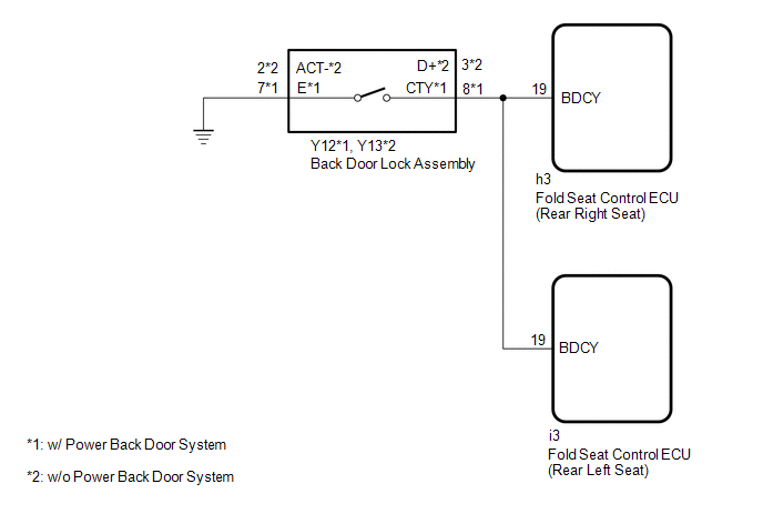
The fold seat control ECU receives the switch operation signal, driving condition signal and back door open/close signal from the back door lock assembly. The fold seat control ECU actives the rear seat according to these signals.
WIRING DIAGRAM
PROCEDURE
| 1. | CHECK BACK DOOR LOCK ASSEMBLY (BACK DOOR COURTESY LIGHT SWITCH) |
(a) Check that the luggage compartment light is on and off according to the back door operation.
OK:
Luggage compartment light is on and off normally according to the back door operation.
| NG | .gif) | GO TO LIGHTING SYSTEM |
|
.gif)
| 2. | CHECK HARNESS AND CONNECTOR (BACK DOOR LOCK ASSEMBLY - FOLD SEAT CONTROL ECU AND BODY GROUND) |
(a) Disconnect the Y12*1 or Y13*2 back door lock assembly connector.
- *1: w/ Power Back Door System
- *2: w/o Power Back Door System
(b) Disconnect the h3*1 or i3*2 fold seat control ECU connector.
- *1: Rear Right Seat
- *2: Rear Left Seat
(c) Measure the resistance according to the value(s) in the table below.
Standard Resistance:
w/ Power Back Door System (Rear Right Seat)
| Tester Connection | Condition | Specified Condition |
|---|---|---|
| Y12-8 (CTY) - h3-19 (BDCY) | Always | Below 1 Ω |
| Y12-7 (E) - Body ground | Always | Below 1 Ω |
| Y12-8 (CTY) or h3-19 (BDCY) - Body ground | Always | 10 kΩ or higher |
w/o Power Back Door System (Rear Right Seat)
| Tester Connection | Condition | Specified Condition |
|---|---|---|
| Y13-3 (D+) - h3-19 (BDCY) | Always | Below 1 Ω |
| Y13-2 (ACT-) - Body ground | Always | Below 1 Ω |
| Y13-3 (D+) or h3-19 (BDCY) - Body ground | Always | 10 kΩ or higher |
w/ Power Back Door System (Rear Left Seat)
| Tester Connection | Condition | Specified Condition |
|---|---|---|
| Y12-8 (CTY) - i3-19 (BDCY) | Always | Below 1 Ω |
| Y12-7 (E) - Body ground | Always | Below 1 Ω |
| Y12-8 (CTY) or i3-19 (BDCY) - Body ground | Always | 10 kΩ or higher |
w/o Power Back Door System (Rear Left Seat)
| Tester Connection | Condition | Specified Condition |
|---|---|---|
| Y13-3 (D+) - i3-19 (BDCY) | Always | Below 1 Ω |
| Y13-2 (ACT-) - Body ground | Always | Below 1 Ω |
| Y13-3 (D+) or i3-19 (BDCY) - Body ground | Always | 10 kΩ or higher |
| OK | | PROCEED TO NEXT SUSPECTED AREA SHOWN IN PROBLEM SYMPTOMS TABLE |
| NG | | REPAIR OR REPLACE HARNESS OR CONNECTOR |
READ NEXT:
 Fold Seat Switch Circuit
DESCRIPTION When the fold seat switch is operated, a switch operation signal is sent to the fold seat control ECU. The ECU receives switch operation signals from each switch and activates the reclinin
Folding Motor Circuit
DESCRIPTION The fold seat control ECU receives switch operation signals from the No. 1 and No. 2 fold seat switches and activates the power seat motors. At this time, the Hall IC detects the actuation
Reclining Motor Circuit
DESCRIPTION The fold seat control ECU receives switch operation signals from the No. 1 and No. 2 fold seat switches and rear power seat switch and activates the power seat motors. At this time, the Ha
SEE MORE:
Visual Mute Signal Circuit between Radio Receiver and Multi-display
DESCRIPTION The radio receiver assembly sends a visual mute signal to the multi-display assembly. As a result, a black screen is inserted when the screen changes so that noise and distorted images are not displayed. When an open exists in the circuit, noise and distorted images will be displayed ins
Installation
INSTALLATION PROCEDURE 1. INSTALL RADIO RECEIVER ASSEMBLY 2. INSTALL NAVIGATION ECU Click here 3. INSTALL NO. 1 RADIO BRACKET (a) w/ Navigation System (1) Install the No. 1 radio bracket with the 5 screws. (b) w/o Navigation System (1) Install the No. 1 radio bracket with the 3 screws. 4. INSTALL
