Lexus NX: Rear Motor Resolver Circuit
DESCRIPTION
The cause of this malfunction may be the rear motor resolver.
Check the rear motor resolver internal resistance and connection condition from the inverter to the resolver.
Related Parts Check| Area | Inspection | Step |
|---|---|---|
| Wire harness and connector between the inverter and rear motor resolver | Check for short circuit between wire harness and +B side. | 1 |
| Resolver, wire harness, connector | Check the resolver internal resistance (include wire harness), body ground resistance, and connector connection condition. | 2, 3 |
| Wire harness | Check for open or short circuit in wire harness. | 4 |
SYSTEM DESCRIPTION
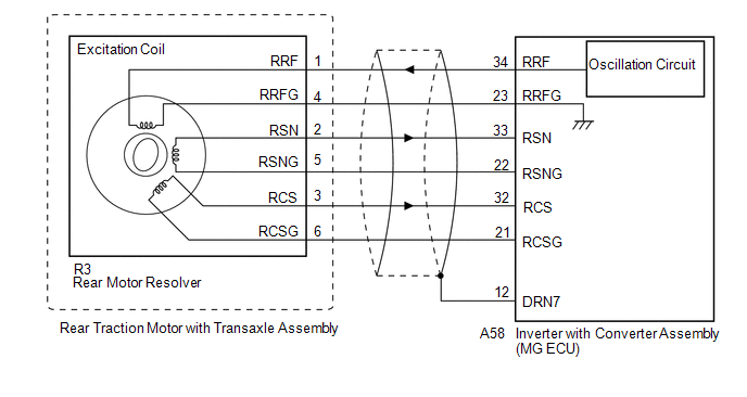
A resolver is a sensor that is used to detect the position of the magnetic poles the rotor of a motor generator. Knowing the position of the poles is indispensable for ensuring precise control of the rear motor (MGR).
Each resolver contains a stator that has an excitation coil and 2 detection coils (S, C). The gap between the stator and rotor changes as the rotor turns because the rotor is oval shaped. An alternating current with a predetermined frequency flows through the excitation coil, and detection coils S and C output alternating currents in accordance with the sensor rotor position.
The inverter with converter assembly (MG ECU) detects the absolute position of the rotor according to the phases of detection coils S and C and the heights of their waveforms. Furthermore, the CPU calculates the amount of change in the position within a predetermined length of time, in order to use the resolver as a speed sensor. The MG ECU monitors signals output from the rear motor resolver and detects malfunctions.
.png)
WIRING DIAGRAM
CAUTION / NOTICE / HINT
This step is referenced from the procedures for each DTC.
If the inspection results below are normal, perform the next procedure for the referenced DTC.
CAUTION:
- Before inspecting the high-voltage system or disconnecting the low voltage connector of the inverter with converter assembly, take safety precautions such as wearing insulated gloves and removing the service plug grip to prevent electrical shocks. After removing the service plug grip, put it in your pocket to prevent other technicians from accidentally reconnecting it while you are working on the high-voltage system.
-
After removing the service plug grip, wait for at least 10 minutes before touching any of the high-voltage connectors or terminals. After waiting for 10 minutes, check the voltage at the terminals in the inspection point in the inverter with converter assembly. The voltage should be 0 V before beginning work.
Click here
.gif)
HINT:
Waiting for at least 10 minutes is required to discharge the high-voltage capacitor inside the inverter with converter assembly.
NOTICE:
After turning the power switch off, waiting time may be required before disconnecting the cable from the negative (-) auxiliary battery terminal. Therefore, make sure to read the disconnecting the cable from the negative (-) auxiliary battery terminal notices before proceeding with work.
Click here
HINT:
- If the problem symptom cannot be reproduced, performing a road test on a road on which the vehicle tends to vibrate will make it easier to reproduce the symptom.
- If the resolver is malfunctioning, the vehicle may not drive smoothly.
PROCEDURE
| 1. | CHECK HARNESS AND CONNECTOR (INVERTER WITH CONVERTER ASSEMBLY - REAR MOTOR RESOLVER) |
CAUTION:
Be sure to wear insulated gloves.
(a) Check that the service plug grip is not installed.
NOTICE:
After removing the service plug grip, do not turn the power switch on (READY), unless instructed by the repair manual because this may cause a malfunction.
(b) Disconnect the A58 inverter with converter assembly connector.
Click here
(c) Connect the cable to the negative (-) auxiliary battery terminal.
(d) Turn the power switch on (IG).
| (e) Measure the voltage according to the value(s) in the table below. Standard Voltage:
NOTICE: Turning the power switch on (IG) with the low voltage connector of the inverter with converter assembly disconnected causes other DTCs to be stored. Clear the DTCs after performing this inspection. |
|
(f) Turn the power switch off.
(g) Disconnect the cable from the negative (-) auxiliary battery terminal.
(h) Reconnect the A58 inverter with converter assembly connector.
| NG | .gif) | REPAIR OR REPLACE HARNESS OR CONNECTOR |
|
.gif)
| 2. | CHECK REAR MOTOR RESOLVER |
CAUTION:
Be sure to wear insulated gloves.
(a) Check that the service plug grip is not installed.
NOTICE:
After removing the service plug grip, do not turn the power switch on (READY), unless instructed by the repair manual because this may cause a malfunction.
(b) Disconnect the A58 inverter with converter assembly connector.
| (c) Measure the resistance according to the value(s) in the table below. Standard Resistance (Check for Open):
Standard Resistance (Check for Short):
|
|

(d) Connect the A58 inverter with converter assembly connector.
| OK | | REAR MOTOR RESOLVER CIRCUIT NORMAL (PERFORM NEXT STEP FOR REFERENCED DTC) |
|
| 3. | CHECK CONNECTOR CONNECTION CONDITION (REAR MOTOR RESOLVER CONNECTOR) |
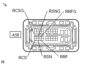
| (a) Check the connection condition of the rear motor resolver connector and the contact pressure of each terminal. Check the terminals for deformation, and check the connector for water ingress and foreign matter. Click here OK: - The connector is connected securely. - The terminals are not deformed and are connected securely. - No water or foreign matter in the connector. |
|
.png)
| Result | Proceed to |
|---|---|
| OK | A |
| NG (The connector is not connected securely.) | B |
| NG (The terminals are not making secure contact or are deformed, or water or foreign matter exists in the connector.) | C |
| B | | CONNECT SECURELY |
| C | | REPAIR OR REPLACE HARNESS OR CONNECTOR |
|
| 4. | INSPECT REAR TRACTION MOTOR WITH TRANSAXLE ASSEMBLY (REAR MOTOR RESOLVER) |
(a) Disconnect the R3 rear motor resolver connector.
| (b) Measure the resistance according to the value(s) in the table below. Standard Resistance (Check for Open):
Standard Resistance (Check for Short):
HINT: The rear motor resolver is not available as a supply part. If it requires replacement, replace the rear traction motor with transaxle assembly. |
|
.png)
(c) Reconnect the R3 rear motor resolver connector.
| OK | | REPAIR OR REPLACE HARNESS OR CONNECTOR |
| NG | | REPLACE REAR TRACTION MOTOR WITH TRANSAXLE ASSEMBLY |
READ NEXT:
 Rear Motor High-voltage Circuit
DESCRIPTION The cause of this malfunction may be the high-voltage circuit of the rear motor. Check the rear motor internal resistance and the connection condition of the high-voltage line between the
Shut Down Signal Circuit
DESCRIPTION The cause of the malfunction may be a shutdown signal. Check whether there is a shutdown signal +B short circuit. Related Parts Check Area Inspection Step HSDN terminal voltage
Inverter Low-voltage Circuit
DESCRIPTION The cause of the malfunction may be the low-voltage circuit. Check whether there is an open circuit in the inverter +B low-voltage power source system or a problem in the communication bet
SEE MORE:
Parts Location
PARTS LOCATION ILLUSTRATION *A w/ Blind Spot Monitor System - - *1 FRONT TELEVISION CAMERA ASSEMBLY *2 REAR TELEVISION CAMERA ASSEMBLY *3 SIDE TELEVISION CAMERA ASSEMBLY RH *4 SIDE TELEVISION CAMERA ASSEMBLY LH *5 BRAKE BOOSTER WITH MASTER CYLINDER ASSEMBLY (SKID
ECM / PCM Processor (P0606)
MONITOR DESCRIPTION The ECM continuously monitors its main and sub CPUs. This self-check ensures that the ECM is functioning properly. If outputs from these CPUs are different and deviate from the standard, the ECM will illuminate the MIL and store this DTC. DTC No. Detection Item DTC Detecti
