Lexus NX: Rear Seat Belt Warning Light Malfunction
DESCRIPTION
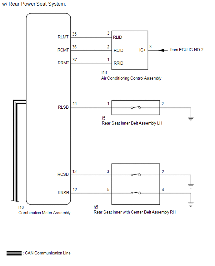
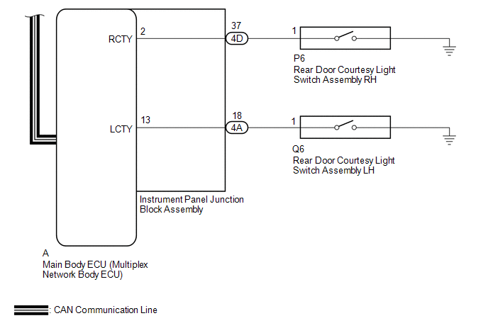
The main body ECU (multiplex network body ECU) detects whether either rear door is open or closed based on the condition of the left and right courtesy light switches and then sends the rear door status signal to the combination meter assembly. The combination meter assembly detects the rear seat belt state. The rear seat belt warning lights on the air conditioning control assembly illuminate or turn off in accordance with the rear door state, vehicle speed and rear seat belt state.
WIRING DIAGRAM
CAUTION / NOTICE / HINT
NOTICE:
-
The seat belt warning system uses the CAN communication system. First, confirm that there are no malfunctions in the CAN communication system. Refer to the How to Proceed with Troubleshooting procedure.
Click here
.gif)
- Inspect the fuses for circuits related to this system before performing the following procedure.
- When replacing the combination meter assembly, make sure to replace it with a new one.
PROCEDURE
| 1. | READ VALUE USING TECHSTREAM (RR Door Courtesy SW, RL Door Courtesy SW) |
(a) Connect the Techstream to the DLC3.
(b) Turn the power switch on (IG).
(c) Turn the Techstream on.
(d) Enter the following menus: Body Electrical / Main Body / Data List.
(e) Read the Data List according to the display on the Techstream.
Body Electrical > Main Body > Data List| Tester Display | Measurement Item | Range | Normal Condition | Diagnostic Note |
|---|---|---|---|---|
| RR Door Courtesy SW | Rear door courtesy light switch RH | ON or OFF | ON: Rear door RH open OFF: Rear door RH closed | - |
| RL Door Courtesy SW | Rear door courtesy light switch LH | ON or OFF | ON: Rear door LH open OFF: Rear door LH closed | - |
| Tester Display |
|---|
| RR Door Courtesy SW |
| RL Door Courtesy SW |
OK:
The Techstream display changes correctly in response to the rear door condition.
| NG | .gif) | GO TO LIGHTING SYSTEM |
|
.gif)
| 2. | READ VALUE USING TECHSTREAM (2nd-Row Seatbelt Buckle [R], 2nd-Row Seatbelt Buckle [L], 2nd-Row Seatbelt Buckle [C]) |
(a) Connect the Techstream to the DLC3.
(b) Turn the power switch on (IG).
(c) Turn the Techstream on.
(d) Enter the following menus: Body Electrical / Combination Meter / Data List.
(e) Read the Data List according to the display on the Techstream.
Body Electrical > Combination Meter > Data List| Tester Display | Measurement Item | Range | Normal Condition | Diagnostic Note |
|---|---|---|---|---|
| 2nd-Row Seatbelt Buckle (R) | Rear seat belt buckle switch RH signal | ON or OFF | OFF: Rear RH seat belt fastened ON: Rear RH seat belt unfastened | - |
| 2nd-Row Seatbelt Buckle (L) | Rear seat belt buckle switch LH signal | ON or OFF | OFF: Rear LH seat belt fastened ON: Rear LH seat belt unfastened | - |
| 2nd-Row Seatbelt Buckle (C) | Rear seat center belt switch buckle signal | ON or OFF | OFF: Rear center seat belt fastened ON: Rear center seat belt unfastened | - |
| Tester Display |
|---|
| 2nd-Row Seatbelt Buckle (R) |
| 2nd-Row Seatbelt Buckle (L) |
| 2nd-Row Seatbelt Buckle (C) |
| Result | Proceed to |
|---|---|
| ON or OFF is displayed on the Techstream screen according to the rear seat belt condition | A |
| ON or OFF is not displayed normally on the Techstream screen according to the rear RH seat belt condition | B |
| ON or OFF is not displayed normally on the Techstream screen according to the rear center seat belt condition | |
| ON or OFF is not displayed normally on the Techstream screen according to the rear LH seat belt condition | C |
| B | | GO TO STEP 6 |
| C | | GO TO STEP 8 |
|
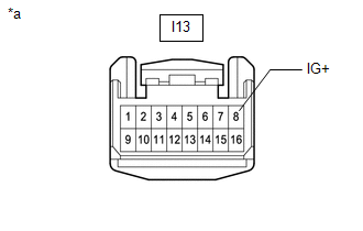
| 3. | CHECK HARNESS AND CONNECTOR (AIR CONDITIONING CONTROL ASSEMBLY - BATTERY) |
| (a) Disconnect the air conditioning control assembly connector. |
|
(b) Measure the voltage according to the value(s) in the table below.
Standard Voltage:
| Tester Connection | Switch Condition | Specified Condition |
|---|---|---|
| I13-8 (IG+) - Body ground | Power switch on (IG) | 11 to 14 V |
| Power switch off | Below 1 V |
| NG | | REPAIR OR REPLACE HARNESS OR CONNECTOR |
|
| 4. | INSPECT AIR CONDITIONING CONTROL ASSEMBLY |
(a) Remove the air conditioning control assembly.
Click here
(b) Inspect the air conditioning control assembly.
Click here
| NG | | REPLACE AIR CONDITIONING CONTROL ASSEMBLY |
|
| 5. | CHECK HARNESS AND CONNECTOR (AIR CONDITIONING CONTROL ASSEMBLY - COMBINATION METER ASSEMBLY) |
(a) Disconnect the I13 air conditioning control assembly connector.
(b) Disconnect the I10 combination meter assembly connector.
(c) Measure the resistance according to the value(s) in the table below.
Standard Resistance:
| Tester Connection | Condition | Specified Condition |
|---|---|---|
| I10-35 (RLMT) - I13-3 (RLID) | Always | Below 1 Ω |
| I10-35 (RLMT) or I13-3 (RLID) - Body ground | Always | 10 kΩ or higher |
| I10-36 (RCMT) - I13-2 (RCID) | Always | Below 1 Ω |
| I10-36 (RCMT) or I13-2 (RCID) - Body ground | Always | 10 kΩ or higher |
| I10-37 (RRMT) - I13-1 (RRID) | Always | Below 1 Ω |
| I10-37 (RRMT) or I13-1 (RRID) - Body ground | Always | 10 kΩ or higher |
| OK | | REPLACE COMBINATION METER ASSEMBLY |
| NG | | REPAIR OR REPLACE HARNESS OR CONNECTOR |
| 6. | INSPECT REAR SEAT INNER WITH CENTER BELT ASSEMBLY RH |
(a) Remove the rear seat inner with center belt assembly RH.
Click here
(b) Inspect the rear seat inner with center belt assembly RH.
Click here
| NG | | REPLACE REAR SEAT INNER WITH CENTER BELT ASSEMBLY RH |
|
| 7. | CHECK HARNESS AND CONNECTOR (REAR SEAT INNER WITH CENTER BELT ASSEMBLY RH - COMBINATION METER ASSEMBLY AND BODY GROUND) |
(a) Disconnect the h5 rear seat inner with center belt assembly RH connector.
(b) Disconnect the I10 combination meter assembly connector.
(c) Measure the resistance according to the value(s) in the table below.
Standard Resistance:
| Tester Connection | Condition | Specified Condition |
|---|---|---|
| h5-3 - I10-13 (RCSB) | Always | Below 1 Ω |
| h5-3 or I10-13 (RCSB) - Body ground | Always | 10 kΩ or higher |
| h5-5 - I10-12 (RRSB) | Always | Below 1 Ω |
| h5-5 or I10-12 (RRSB) - Body ground | Always | 10 kΩ or higher |
| h5-4 - Body ground | Always | Below 1 Ω |
| h5-2 - Body ground | Always | Below 1 Ω |
| OK | | REPLACE COMBINATION METER ASSEMBLY |
| NG | | REPAIR OR REPLACE HARNESS OR CONNECTOR |
| 8. | INSPECT REAR SEAT INNER BELT ASSEMBLY LH |
(a) Remove the rear seat inner belt assembly LH.
Click here
(b) Inspect the rear seat inner belt assembly LH.
Click here
| NG | | REPLACE REAR SEAT INNER BELT ASSEMBLY LH |
|
| 9. | CHECK HARNESS AND CONNECTOR (REAR SEAT INNER BELT ASSEMBLY LH - COMBINATION METER ASSEMBLY AND BODY GROUND) |
(a) Disconnect the i5 rear seat inner belt assembly connector.
(b) Disconnect the I10 combination meter assembly connector.
(c) Measure the resistance according to the value(s) in the table below.
Standard Resistance:
| Tester Connection | Condition | Specified Condition |
|---|---|---|
| i5-1 - I10-14 (RLSB) | Always | Below 1 Ω |
| i5-1 or I10-14 (RLSB) - Body ground | Always | 10 kΩ or higher |
| i5-2 - Body ground | Always | Below 1 Ω |
| OK | | REPLACE COMBINATION METER ASSEMBLY |
| NG | | REPAIR OR REPLACE HARNESS OR CONNECTOR |
READ NEXT:
 Tongue Plate Stopper
ComponentsCOMPONENTS ILLUSTRATION *1 TONGUE PLATE STOPPER - - ● Non-reusable part - - ReplacementREPLACEMENT PROCEDURE 1. REMOVE TONGUE PLATE STOPPER (a) Slide the tongue
SEE MORE:
ABS Warning Light does not Come ON
DESCRIPTION The skid control ECU (brake booster with master cylinder assembly) is connected to the combination meter assembly via CAN communication. CAUTION / NOTICE / HINT NOTICE: When replacing the skid control ECU (brake booster with master cylinder assembly), perform initialization and calibrati
Hybrid Battery Voltage System Isolation Fault (P0AA6-611)
DESCRIPTION This DTC is stored if there is insulation malfunction in the high-voltage circuit in the air conditioning system. Possible causes are poor insulation in the compressor with motor assembly, or mixing of any oil other than ND-OIL 11 in the refrigerant cycle. A high-voltage motor is built i
