Lexus NX: Precaution
PRECAUTION
NOTICE:
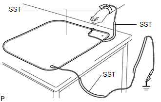
When disassembling the fog light assembly, use static electricity countermeasures SST (desktop anti-static mat set) and observe all precautions to prevent damage to the system by electrostatic discharge (ESD).
STATIC ELECTRICITY COUNTERMEASURES SST
SST:Desktop anti-static mat set (09890-47010)
-
Wristband
SST:
09891-04020
-
Wristband connection wire (No. 1 grounding wire)
SST:
09891-04030
-
Anti-static mat
SST:
09891-04010
-
Ground connection wire (No. 2 grounding wire)
SST:
09891-04040
PRECAUTIONS DURING REPLACEMENT
(a) Precautions during procedures:
(1) Before performing any procedures, touch an unpainted metal part or ground bolt of the vehicle to eliminate any static electricity.
(2) To prevent damage to electrical equipment, disconnect the battery power supply before installing and removing electrical equipment.
(3) Never touch the electronic parts of a printed wire board or the pins of an integrated circuit.
(4) When performing procedures, do not allow clothing to come near or contact parts.
(b) Wear the SST (wristband) firmly on your wrist.
SST:
09891-04020
(c) Connect the SST (No. 2 grounding wire) and SST (anti-static mat) to an appropriate grounding point in the workspace and on the work table.
SST:
09891-04040
09891-04010
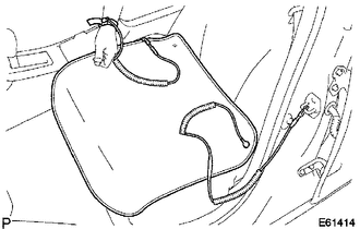
HINT:
When working inside the vehicle:
Connect SST (No. 2 grounding wire) to the unpainted metal part of a grounded bolt, etc.
(d) Connect SST (No. 1 grounding wire), SST (wristband) and SST (anti-static mat).
SST:
09891-04030
(e) Always place the fog light assembly and its components on SST (anti-static mat).
READ NEXT:
 Components
COMPONENTS ILLUSTRATION *1 FOG LIGHT ASSEMBLY LH - - ILLUSTRATION *1 FOG LIGHT GASKET *2 FOG LIGHT LENS LH *3 FOG LIGHT UNIT LH *4 PIVOT COLLAR ● Non-reusable
Removal
REMOVAL CAUTION / NOTICE / HINT HINT:
Use the same procedure for the RH and LH sides.
The procedure described below is for the LH side.
PROCEDURE 1. REMOVE FRONT BUMPER ASSEMBLY Click here 2
Disassembly
DISASSEMBLY PROCEDURE 1. PRECAUTION NOTICE:
Be sure to read Precaution thoroughly before servicing.
Click here
Handle components indoors as much as possible to prevent foreign matter from enter
SEE MORE:
Installation
INSTALLATION PROCEDURE 1. INSTALL AIR CONDITIONING THERMISTOR ASSEMBLY (HUMIDITY SENSOR) *1 Stopper *2 Bracket (a) Attach the 2 brackets, and carefully install the air conditioning thermistor assembly (humidity sensor) to the glass surface, preventing air bubbles from forming between
Customize Parameters
CUSTOMIZE PARAMETERS CUSTOMIZE SLIDING ROOF SYSTEM HINT: The following items can be customized. NOTICE:
When the customer requests a change in a function, first make sure that the function can be customized.
Be sure to make notes of the current settings before customizing.
When troubleshootin
