Lexus NX: Reassembly
REASSEMBLY
CAUTION / NOTICE / HINT
NOTICE:
- Handle components indoors as much as possible to prevent foreign matter from entering and adhering to fog light assembly components.
- Do not reuse parts which have reduced fastening ability due to thread damage.
- When installing components, make sure that the wire harness is not pinched or pulled.
- Do not use solvent to clean components. Only clean them with a dry cloth.
HINT:
- Use the same procedure for the RH and LH sides.
- The procedure listed below is for the LH side.
PROCEDURE
1. INSTALL FOG LIGHT UNIT LH
NOTICE:
- Prevention of static electricity is required during this procedure.
- Use static electricity countermeasures SST (desktop anti-static mat set) and observe all precautions to prevent damage to the system by electrostatic discharge (ESD).
- Perform work using clean rubber gloves.
- Do not touch the fog light unit LH with bare hands.
- Do not allow metallic surfaces to become dirty, as such surfaces become damaged even if they are only lightly wiped with a soft cloth.
- If there are fingerprints on the inner surface of the lens, lightly wiped with a soft cloth.
- Do not use solvent to clean components. Only clean them with a dry cloth.
SST: 09890-47010
09891-04010
09891-04020
09891-04030
09891-04040
(a) Set the fog light unit LH to the aiming screw.
| (b) While holding the fog light unit LH with one hand so that it does not fall over, tighten the aiming screw same number of rotations recorded when removing it to connect the aiming screw. |
|
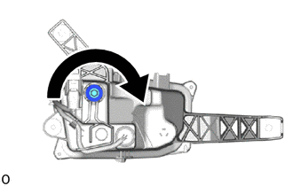
| (c) Attach the 2 pivot collars. |
|
| (d) Tighten the aiming screw 20 rotations. |
|
(e) Connect the connector.
2. INSTALL FOG LIGHT GASKET
NOTICE:
- The fog light gasket must not be reused.
- Perform work using clean rubber gloves.
- Do not touch the inner surface of the lens and metallic surfaces as much as possible, or they may become dirty.
- Do not allow metallic surfaces to become dirty, as such surfaces become damaged even if they are only lightly wiped with a soft cloth.
- If there are fingerprints on the inner surface of the lens, lightly wiped with a soft cloth.
- Do not use solvent to clean components. Only clean them with a dry cloth.
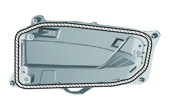
(a) Clean the fog light gasket installation groove.
.png) | Area to Clean |
(b) Prepare 2 screwdrivers, fold a piece of peeling paper over the tip of each screwdriver and fix the pieces of peeling paper in place with tape.
HINT:
Use the peeling paper that is supplied with the fog light gasket.
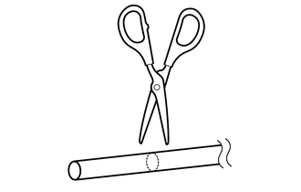
| (c) Using scissors, cut the headlight lens gasket at a 90°. |
|
(d) Starting at the lower side of the fog light lens LH claw attaching point, set the fog light gasket into the straight groove counterclockwise until it meets the corner groove.
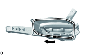
 | Starting Point |
NOTICE:
Lightly set the gasket in place without pulling.
(e) Using 2 screwdrivers with their tips wrapped with peeling paper, push the fog light gasket into the bottom of the groove.
(f) Set the fog light gasket into the corner groove and using 2 screwdrivers with their tips wrapped with peeling paper, push the gasket into the bottom of the groove.
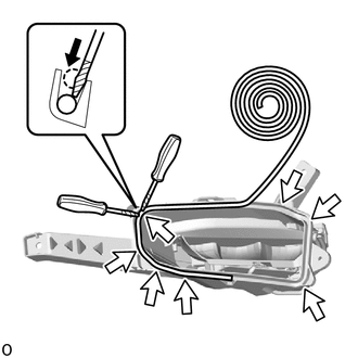
.png) | Corner Groove |
NOTICE:
- Lightly set the gasket in place without pulling.
- If the fog light gasket is set while pulled, the gasket will be pushed up at the corner groove.
(g) Repeat the following order while working in a circle back to the starting point.
(1) Set fog light gasket into straight groove.
(2) Push into bottom of groove.
(3) Set into corner groove.
(4) Push into bottom of groove.
(h) Using scissors, cut the fog gasket at a 45° angle at the starting point so that the gasket overlaps itself 10 mm (0.394 in.) or more and set the gasket in place.
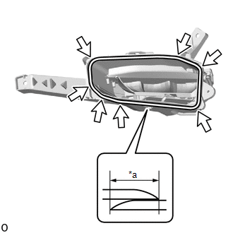
| *a | 10 mm (0.394 in.) |
| | Corner Groove |
(i) Check the installation condition of the fog light gasket.
OK:
Gasket not pushed up or protruding.
No gap where gasket overlaps.
NOTICE:
Check the corners carefully since the gasket can easily become pushed up in those areas.
3. INSTALL FOG LIGHT LENS LH
NOTICE:
- Perform work using clean rubber gloves.
- Do not touch the fog light lens LH with bare hands.
- If dirty, lightly wipe with a soft cloth.
(a) Clean the fog light gasket contact surface.
| | Area to Clean |
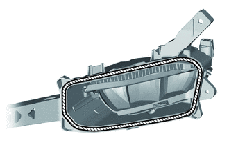
(b) Set the fog light lens LH in place.
NOTICE:
Set the fog light lens LH in the middle of the fog light lens gasket as shown in the illustration.
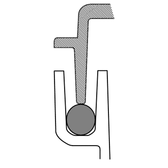
.png) | Fog Light Housing |
.png) | Fog Light Lens Gasket |
| | Fog Light Lens |
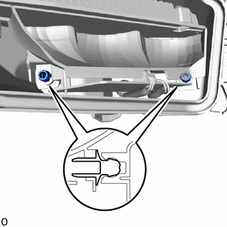
(c) Attach the 2 claws.
| (d) Using a T20H "TORX" screwdriver, install the screw. |
|
.png)
(e) Install the 3 screws.
(f) Check that the fog light gasket installation condition.
OK:
Gasket contacts fog light lens LH and does not protrude out.
READ NEXT:
 Installation
INSTALLATION CAUTION / NOTICE / HINT HINT:
Use the same procedure for the RH and LH sides.
The procedure described below is for the LH side.
PROCEDURE 1. INSTALL FOG LIGHT ASSEMBLY LH (a) Inst
Front Side Marker Light Bulb(for Single Beam Headlight)
ReplacementREPLACEMENT CAUTION / NOTICE / HINT HINT:
Use the same procedure for the RH and LH sides.
The procedure listed below is for the LH side.
PROCEDURE 1. REMOVE FRONT SIDE MARKER LIGHT
Front Turn Signal Light Bulb(for Bulb Type Turn Signal Light)
ReplacementREPLACEMENT CAUTION / NOTICE / HINT HINT:
Use the same procedure for the RH and LH sides.
The procedure listed below is for the LH side.
PROCEDURE 1. REMOVE FRONT RADIATOR SIDE AIR
SEE MORE:
Headlight Swivel ECU LH Communication (B2410,B2411,B2424,B2425)
DESCRIPTION Each headlight ECU sub-assembly and headlight swivel and leveling motor communicate via LIN communication. The headlight swivel and leveling motor operates according to power supplied and automatic headlight beam level control signals from its respective headlight ECU sub-assembly and se
Switch Lights of Remote Touch do not Illuminate
DESCRIPTION Power is supplied to the remote touch illumination when the light control switch is in the tail or head position. WIRING DIAGRAM CAUTION / NOTICE / HINT NOTICE: Inspect the fuse for circuits related to this system before performing the following procedure. PROCEDURE 1. CONFIRM SYM
