
Lexus NX: Front Side Marker Light Bulb(for Single Beam Headlight)
Replacement
REPLACEMENT
CAUTION / NOTICE / HINT
HINT:
- Use the same procedure for the RH and LH sides.
- The procedure listed below is for the LH side.
PROCEDURE
1. REMOVE FRONT SIDE MARKER LIGHT SOCKET
| (a) Disconnect the connector. |
|
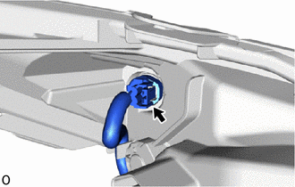
(b) Turn the front side marker light socket counterclockwise until the matchmark is aligned with the unlock position mark to remove it.
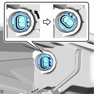
| *1 | Matchmark |
| *2 | Unlock Position Mark |
.png) | Counterclockwise |
2. REMOVE FRONT SIDE MAKER LIGHT BULB
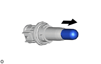
| (a) Remove the front side marker light bulb from the front side marker light socket. |
|
3. INSTALL FRONT SIDE MAKER LIGHT BULB
(a) Install the front side marker light bulb to the front side marker light socket.
4. INSTALL FRONT SIDE MARKER LIGHT SOCKET
(a) Align the matchmark of the front side marker light socket to the unlock position mark, and then rotate the front side marker light socket clockwise until the lock position mark to install it.
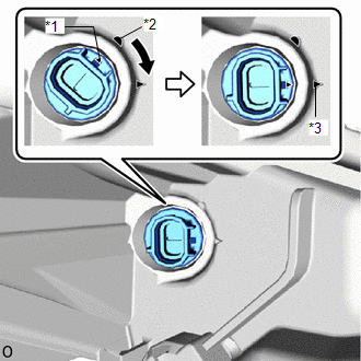
| *1 | Matchmark |
| *2 | Unlock Position Mark |
| *3 | Lock Position Mark |
| | Clockwise |
(b) Connect the connector.
READ NEXT:
 Front Turn Signal Light Bulb(for Bulb Type Turn Signal Light)
ReplacementREPLACEMENT CAUTION / NOTICE / HINT HINT:
Use the same procedure for the RH and LH sides.
The procedure listed below is for the LH side.
PROCEDURE 1. REMOVE FRONT RADIATOR SIDE AIR
Hazard Warning Switch
InspectionINSPECTION PROCEDURE 1. INSPECT AIR CONDITIONING CONTROL ASSEMBLY (HAZARD WARNING SWITCH) (a) Remove the air conditioning control assembly. Click here (b) Inspect the hazard warning swit
SEE MORE:
Problem Symptoms Table
PROBLEM SYMPTOMS TABLE NOTICE:
Recognition code registration is necessary when replacing the main body ECU (multiplex network body ECU).
If the main body ECU (multiplex network body ECU) is replaced, refer to Registration.
Click here HINT:
Use the table below to help determine the cau
Data Signal Circuit between Radio Receiver and Stereo Jack Adapter
DESCRIPTION The No. 1 stereo jack adapter assembly sends the sound data signal or image data signal from a USB device to the radio receiver assembly via this circuit. WIRING DIAGRAM PROCEDURE 1. CHECK HARNESS AND CONNECTOR (RADIO RECEIVER ASSEMBLY - NO. 1 STEREO JACK ADAPTER ASSEMBLY) (
