Lexus NX: Components
Lexus NX Service Manual / Vehicle Interior / Heating / Air Conditioning / Room Temperature Sensor / Components
COMPONENTS
ILLUSTRATION
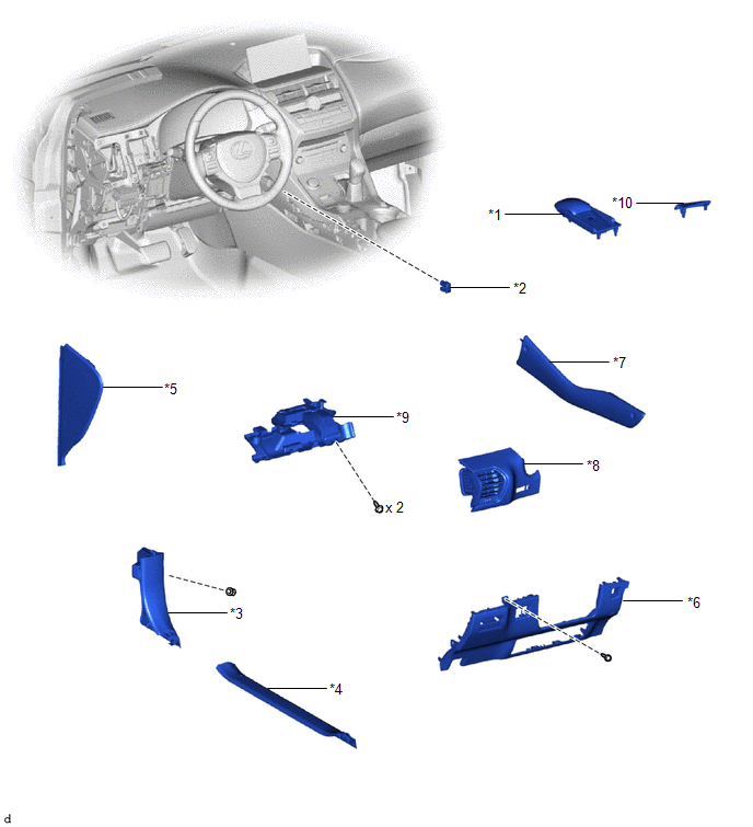
| *1 | CONSOLE ARMREST ASSEMBLY | *2 | COOLER THERMISTOR (ROOM TEMPERATURE SENSOR) |
| *3 | COWL SIDE TRIM BOARD LH | *4 | DOOR SCUFF PLATE ASSEMBLY LH |
| *5 | INSTRUMENT SIDE PANEL LH | *6 | LOWER NO. 1 INSTRUMENT PANEL FINISH PANEL |
| *7 | UPPER NO. 1 CONSOLE PANEL GARNISH | *8 | NO. 1 INSTRUMENT PANEL SAFETY PAD SUB-ASSEMBLY |
| *9 | NO. 1 INSTRUMENT PANEL UNDER COVER SUB-ASSEMBLY | *10 | UPPER REAR CONSOLE PANEL |
READ NEXT:
 Removal
REMOVAL PROCEDURE 1. REMOVE DOOR SCUFF PLATE ASSEMBLY LH Click here 2. REMOVE COWL SIDE TRIM BOARD LH Click here 3. REMOVE CONSOLE ARMREST ASSEMBLY Click here 4. REMOVE UPPER REAR CONSOL
Inspection
INSPECTION PROCEDURE 1. INSPECT COOLER THERMISTOR (ROOM TEMPERATURE SENSOR) (a) Measure the resistance according to the value(s) in the table below. Standard Resistance: Tester Connection Con
Installation
INSTALLATION CAUTION / NOTICE / HINT HINT:
Use the same procedure for RHD and LHD vehicles.
The procedure listed below is for LHD vehicles.
PROCEDURE 1. INSTALL COOLER THERMISTOR (ROOM TEMPERA
SEE MORE:
Taillight Relay Circuit
DESCRIPTION Illumination of the taillights and license plate light is controlled by the main body ECU (multiplex network body ECU). WIRING DIAGRAM CAUTION / NOTICE / HINT NOTICE:
Inspect the fuses for circuits related to this system before performing the following procedure.
Recognition code
Does not Recognize Voice Commands Performed to Contact Support Center
PROCEDURE 1. CHECK COMMUNICATION BASED VOICE RECOGNITION FUNCTION (a) While paying attention to the condition of the spoken voice command, say "Find a gas station in New York" and check that voice recognition is operating normally. HINT:
When the voice command is recognized, the content
© 2016-2026 Copyright www.lexunx.com
