Lexus NX: Removal
REMOVAL
PROCEDURE
1. REMOVE SERVICE PLUG GRIP
Click here .gif)
2. REMOVE NO. 1 ENGINE COVER SUB-ASSEMBLY
Click here
3. REMOVE REAR ENGINE UNDER COVER RH
Click here
4. REMOVE FAN AND GENERATOR V BELT
Click here
5. DISCONNECT RADIATOR RESERVE TANK ASSEMBLY
Click here
6. REMOVE AIR CLEANER CAP SUB-ASSEMBLY
Click here
7. REMOVE AIR CLEANER FILTER ELEMENT SUB-ASSEMBLY
Click here
8. REMOVE AIR CLEANER CASE SUB-ASSEMBLY
Click here
9. DISCONNECT GROUND WIRE
Click here
10. DISCONNECT ENGINE WIRE
(a) Disconnect the 17 connectors and 2 clamps.
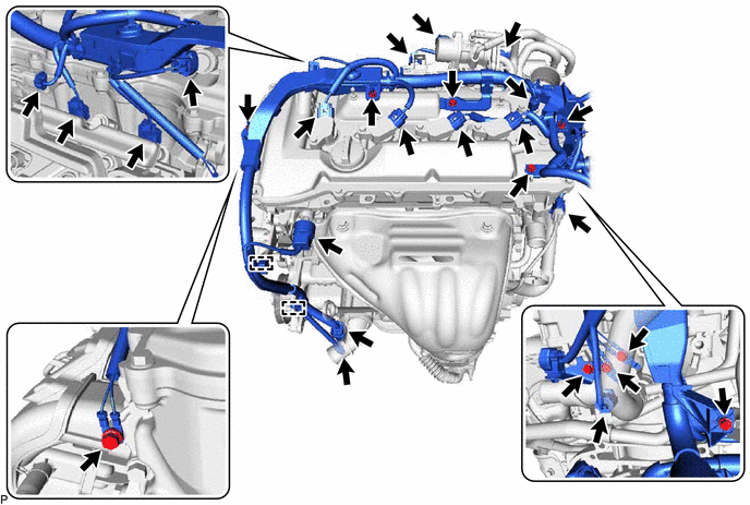
(b) Remove the 7 bolts and 3 nuts and disconnect the engine wire from the engine.
11. REMOVE IGNITION COIL ASSEMBLY
Click here
12. REMOVE CYLINDER HEAD COVER SUB-ASSEMBLY
Click here
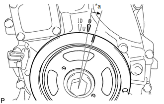
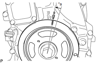
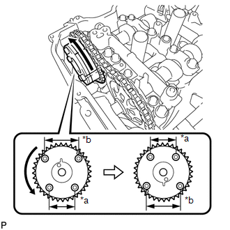
13. SET NO. 1 CYLINDER TO TDC/COMPRESSION
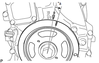
| (a) Turn the crankshaft until the timing mark (groove) of the crankshaft pulley assembly and the timing mark "0" of the timing chain cover are aligned. |
|
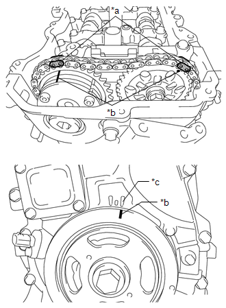
(b) Check that each timing mark of the camshaft timing gear assembly and camshaft timing sprocket are located as shown in the illustration. If not, turn the crankshaft 1 revolution (360°) to align the timing marks as shown in the illustration.
(c) Place paint marks on the chain sub-assembly in alignment with the timing marks on the camshaft timing gear assembly and camshaft timing sprocket.
14. REMOVE TIMING CHAIN COVER PLATE
Click here
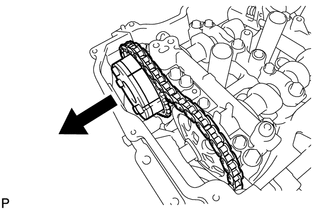
15. REMOVE NO. 1 CHAIN TENSIONER ASSEMBLY
| (a) Turn the crankshaft approximately 10° clockwise. |
|
| (b) Turn the crankshaft approximately 10° counterclockwise. |
|

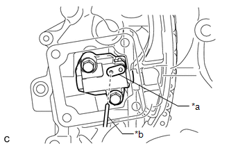
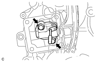
| (c) Align the holes of the stopper plate and No. 1 chain tensioner assembly, and insert a pin into the stopper plate hole to lock the No. 1 chain tensioner assembly. |
|
| (d) Turn the crankshaft approximately 10° clockwise. |
|
| (e) Remove the 2 bolts, No. 1 chain tensioner assembly and gasket. NOTICE: Make sure not to drop the gasket inside the timing chain cover assembly. |
|
| (f) Turn the crankshaft approximately 10° counterclockwise. |
|
16. REMOVE TIMING CHAIN GUIDE
Click here
17. REMOVE TIMING CHAIN COVER TIGHT PLUG
Click here
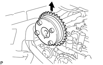
18. REMOVE CAMSHAFT TIMING GEAR ASSEMBLY
| (a) Hold the hexagonal portion of the camshaft with a wrench and remove the bolt from the camshaft. NOTICE: Be careful not to damage the camshaft housing sub-assembly or spark plug tube with the wrench. |
|
| (b) Separate the camshaft timing gear assembly from the camshaft. |
|
| (c) Remove the chain sub-assembly from the camshaft timing gear assembly, and turn the camshaft timing gear assembly approximately 180°. |
|
| (d) Remove the camshaft timing gear assembly. NOTICE: Do not disassemble the camshaft timing gear assembly. |
|
19. REMOVE CAMSHAFT BEARING CAP
| (a) Using several steps, remove the 11 bearing cap bolts in the sequence shown in the illustration. |
|
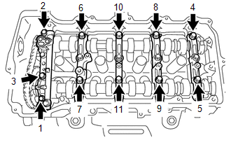
| (b) Using several steps, remove the 10 bearing cap bolts in the sequence shown in the illustration. |
|
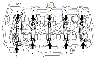
(c) Remove the 5 camshaft bearing caps.
HINT:
Arrange the removed parts in the correct order.
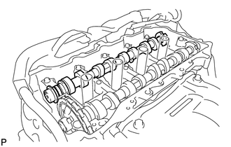
20. REMOVE CAMSHAFT
| (a) Remove the camshaft from the camshaft housing sub-assembly. |
|
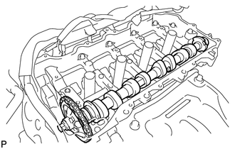
21. REMOVE NO. 2 CAMSHAFT
| (a) Hold up the chain sub-assembly and remove the No. 2 camshaft from the camshaft housing sub-assembly. |
|
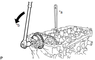
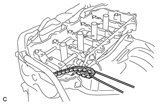
| (b) Suspend the chain sub-assembly with a string or equivalent as shown in the illustration. NOTICE: Be careful not to drop the chain sub-assembly inside the timing chain cover assembly. |
|
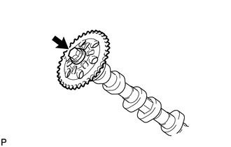
22. REMOVE CAMSHAFT TIMING SPROCKET
(a) Secure the No. 2 camshaft between aluminum plates in a vise.
NOTICE:
Do not damage the No. 2 camshaft.
| (b) Remove the bolt and camshaft timing sprocket. NOTICE: Be careful not to damage the No. 2 camshaft and camshaft timing sprocket. |
|
23. REMOVE OIL CONTROL VALVE FILTER
Click here
24. REMOVE NO. 1 CAMSHAFT BEARING
Click here
25. REMOVE NO. 2 CAMSHAFT BEARING
Click here
READ NEXT:
 Precaution
PRECAUTION HINT:
Any digits beyond the 0.01 mm (1/1000 in.) place for standard, minimum and maximum values should be used as a reference only.
When both standard and maximum or minimum values are
Components
COMPONENTS ILLUSTRATION *1 CONNECTING ROD BEARING *2 CRANKSHAFT *3 CRANKSHAFT BEARING *4 CRANKSHAFT PULLEY SET KEY *5 CRANKSHAFT THRUST WASHER *6 NO. 1 OIL NOZZLE SUB-ASS
SEE MORE:
Disassembly
DISASSEMBLY PROCEDURE 1. REMOVE INTAKE VALVE (a) Using SST and wooden blocks, compress the inner compression spring and remove the valve spring retainer locks. SST: 09202-70020 SST: 09202-00021 (b) Remove the valve spring retainer, inner compression spring and intake valve. HINT: Arra
Removal
REMOVAL CAUTION / NOTICE / HINT NOTICE: While the auxiliary battery is connected, even if the power switch is off, the brake control system activates when the brake pedal is depressed or any door courtesy switch turns on. Therefore, when servicing the brake system components, do not operate the brak
