Lexus NX: Removal
REMOVAL
PROCEDURE
1. PRECAUTION
NOTICE:
After turning the power switch off, there may be a waiting time before disconnecting the negative (-) auxiliary battery terminal.
Click here .gif)
2. REMOVE DECK BOARD ASSEMBLY
Click here
3. REMOVE NO. 3 DECK BOARD SUB-ASSEMBLY
Click here
4. REMOVE REAR DECK FLOOR BOX
Click here
5. REMOVE DECK FLOOR BOX LH
Click here
6. DISCONNECT CABLE FROM NEGATIVE AUXILIARY BATTERY TERMINAL
7. REMOVE REAR SEAT ASSEMBLY
-
for Manual Seat: Click here
-
for Power Seat: Click here
8. REMOVE TONNEAU COVER ASSEMBLY
Click here
9. REMOVE NO. 2 DECK BOARD SUB-ASSEMBLY
Click here
10. REMOVE SPARE TIRE
11. REMOVE DECK FLOOR BOX RH
Click here
12. REMOVE NO. 1 TOOL BOX SUB-ASSEMBLY
Click here
13. REMOVE NO. 2 TOOL BOX SUB-ASSEMBLY
Click here
14. REMOVE REAR FLOOR CARPET
15. REMOVE REAR FLOOR FINISH PLATE
Click here
16. REMOVE BATTERY SERVICE COVER BOARD
-
for Manual Seat: Click here
-
for Power Seat: Click here
17. REMOVE NO. 1 SEAT LEG ASSEMBLY
-
for Manual Seat: Click here
-
for Power Seat: Click here
18. REMOVE REAR DOOR OPENING TRIM WEATHERSTRIP RH
Click here
19. REMOVE ROPE HOOK ASSEMBLY
Click here
20. REMOVE LUGGAGE HOLD BELT STRIKER ASSEMBLY
Click here
21. REMOVE NO. 1 LUGGAGE COMPARTMENT TRIM HOOK
Click here
22. REMOVE UPPER DECK TRIM SIDE BOARD RH
Click here
23. REMOVE DECK TRIM SIDE PANEL ASSEMBLY RH
Click here
24. REMOVE INNER ROOF SIDE GARNISH ASSEMBLY RH
Click here
25. REMOVE TIRE PRESSURE WARNING ECU AND RECEIVER
| (a) Remove the bolt. |
|
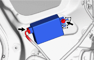
(b) Detach the 2 guides to remove the tire pressure warning ECU and receiver.
(c) Disconnect the connector from the tire pressure warning ECU and receiver.
READ NEXT:
 Installation
INSTALLATION PROCEDURE 1. INSTALL TIRE PRESSURE WARNING ECU AND RECEIVER (a) Connect the connector to the tire pressure warning ECU and receiver. (b) Attach the 2 guides to temporarily install the tir
Components
COMPONENTS ILLUSTRATION *1 TIRE PRESSURE WARNING VALVE AND TRANSMITTER *2 WASHER *3 VALVE CORE *4 GROMMET *5 NUT *6 VALVE CAP N*m (kgf*cm, ft.*lbf): Specified torq
SEE MORE:
Components
COMPONENTS ILLUSTRATION *1 DECK FLOOR BOX LH *2 NO. 3 DECK BOARD SUB-ASSEMBLY *3 REAR DECK FLOOR BOX *4 NEGATIVE AUXILIARY BATTERY TERMINAL N*m (kgf*cm, ft.*lbf): Specified torque - - ILLUSTRATION *1 ABSORBER CONTROL ECU *2 CONNECTOR N*m (kgf*cm, ft
Diagnostic Trouble Code Chart
DIAGNOSTIC TROUBLE CODE CHART Sliding Roof System DTC No. Detection Item Link B2341 Sensor (Motor) Failure B2342 Switch Failure B2343 Position Initialization Incomplete B2344 Position Failure
