
Lexus NX: Removal
REMOVAL
CAUTION / NOTICE / HINT
HINT:
- Use the same procedure for the RH and LH sides.
- The procedures listed below are for the LH side.
PROCEDURE
1. REMOVE FRONT DOOR LOWER OUTSIDE MOULDING SUB-ASSEMBLY LH
HINT:
When removing the front door lower outside moulding sub-assembly LH, heat the front door panel and front door lower outside moulding sub-assembly LH using a heat light.
Standard:
| Item | Temperature |
|---|---|
| Front Door Panel | 40 to 60°C (104 to 140°F) |
| Front Door Lower Outside Moulding Sub-assembly LH | 20 to 30°C (68 to 86°F) |
NOTICE:
Do not heat the front door panel and front door lower outside moulding sub-assembly LH excessively.
(a) Put protective tape around the front door lower outside moulding sub-assembly LH.
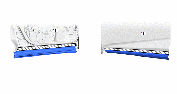
| *1 | Protective Tape | - | - |
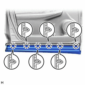
| (b) Using moulding remover D, detach the 6 claws. |
|
| (c) Remove the hole cover. |
|
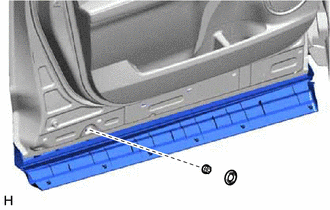
(d) Remove the nut.
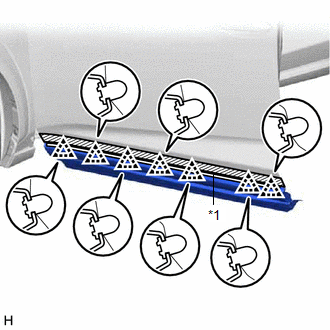
| (e) Using moulding remover D, detach the 7 clips and remove the front door lower outside moulding sub-assembly LH. |
|
READ NEXT:
 Disassembly
DISASSEMBLY CAUTION / NOTICE / HINT HINT:
Use the same procedure for the RH and LH sides.
The procedure listed below is for the LH side.
PROCEDURE 1. REMOVE FRONT DOOR UPPER OUTSIDE MOULDING P
Reassembly
REASSEMBLY CAUTION / NOTICE / HINT HINT:
Use the same procedure for the RH and LH sides.
The procedure listed below is for the LH side.
PROCEDURE 1. INSTALL FRONT DOOR UPPER OUTSIDE MOULDING P
Installation
INSTALLATION CAUTION / NOTICE / HINT HINT:
Use the same procedure for the RH and LH sides.
The procedures listed below are for the LH side.
PROCEDURE 1. INSTALL FRONT DOOR LOWER OUTSIDE MOULDI
SEE MORE:
Dtc Check / Clear
DTC CHECK / CLEAR CHECK FOR DTC (a) Turn the power switch off. (b) Connect the Techstream to the DLC3. (c) Turn the power switch on (IG). (d) Turn the Techstream on. (e) Enter the following menus: Chassis / Air suspension / Trouble Codes. Chassis > Air suspension > Trouble Codes HINT: When fre
Performance Damper
ComponentsCOMPONENTS ILLUSTRATION *1 SUSPENSION TOWER DAMPER - - N*m (kgf*cm, ft.*lbf): Specified torque - - RemovalREMOVAL PROCEDURE 1. REMOVE WINDSHIELD WIPER MOTOR ASSEMBLY Click here 2. REMOVE SUSPENSION TOWER DAMPER (a) Remove the 2 nuts and the suspension tower d
