Lexus NX: Removal
REMOVAL
PROCEDURE
1. REMOVE FRONT BUMPER ASSEMBLY
Click here .gif)
2. REMOVE NO. 3 ENGINE ROOM WIRE
Click here
3. REMOVE CLEARANCE LIGHT ASSEMBLY LH
Click here
4. REMOVE CLEARANCE LIGHT ASSEMBLY RH
HINT:
Use the same procedure described for the LH side.
5. REMOVE HOOD TO FRONT END PANEL SEAL
Click here
6. REMOVE FRONT BUMPER GUARD ASSEMBLY
Click here
7. REMOVE RADIATOR GRILLE SUB-ASSEMBLY
(a) Remove the 6 screws.
(b) Remove the 2 outside moulding retainers.
(c) Detach the 14 claws and 4 guides and remove the radiator grille sub-assembly.
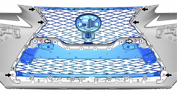
.png) | Screw | .png) | Outside Moulding Retainer |
READ NEXT:
 Disassembly
DISASSEMBLY PROCEDURE 1. REMOVE MILLIMETER WAVE RADAR SENSOR ASSEMBLY Click here 2. REMOVE FRONT TELEVISION CAMERA ASSEMBLY (w/ Panoramic View Monitor System) Click here 3. REMOVE FRONT CENTER ULT
Reassembly
REASSEMBLY PROCEDURE 1. INSTALL NUT (a) Install the 2 nuts. 2. INSTALL RADIATOR GRILLE EMBLEM (a) Attach the claw and guide to install the radiator grille emblem. (b) Ins
Installation
INSTALLATION PROCEDURE 1. INSTALL RADIATOR GRILLE SUB-ASSEMBLY (a) Attach the 14 claws and the 4 guides to install the radiator grille sub-assembly. (b) Install the 2 outside moulding retainers. (c) I
SEE MORE:
High Mounted Stop Light Assembly
ComponentsCOMPONENTS ILLUSTRATION *1 CENTER STOP LIGHT ASSEMBLY *2 REAR SPOILER ASSEMBLY RemovalREMOVAL PROCEDURE 1. REMOVE REAR SPOILER ASSEMBLY Click here 2. REMOVE CENTER STOP LIGHT ASSEMBLY (a) Remove the 2 screws and center stop light assembly. (b) Disconnect
Inspection
INSPECTION PROCEDURE 1. INSPECT REAR LIGHT ASSEMBLY LH (a) Apply battery voltage to the connector and check the light illumination condition. OK: Battery Connection Specified Condition Positive (+) → 2 (B) Negative (-) → 4 (E) Taillight illuminates Positive (+) → 3 (B) Negat
© 2016-2026 Copyright www.lexunx.com
