Lexus NX: Installation
INSTALLATION
PROCEDURE
1. INSTALL REAR BUMPER SIDE SUPPORT LH
| (a) Attach the 2 claws to install the rear bumper side support LH. |
|
(b) Attach the clip.
(c) Install the screw.
2. INSTALL REAR BUMPER SIDE SUPPORT RH
HINT:
Use the same procedure as for the LH side.
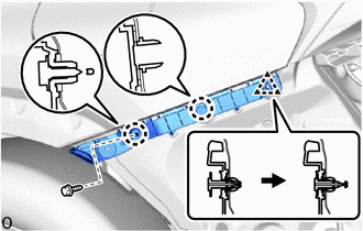
3. INSTALL REAR BUMPER SIDE SEAL LH
| (a) Install the rear bumper side seal LH with 2 new grommets. |
|
.png)
4. INSTALL REAR BUMPER SIDE SEAL RH
HINT:
Use the same procedure as for the LH side.
5. INSTALL REAR BUMPER NO. 1 REINFORCEMENT
| (a) Install the rear bumper No. 1 reinforcement with the 8 bolts. Torque: 37 N·m {377 kgf·cm, 27 ft·lbf} |
|
.png)
6. INSTALL REAR BUMPER COVER
(a) Attach the 16 claws to install the rear bumper cover.
(b) w/ Intuitive Parking Assist System, Hands Free Power Back Door:
(1) Connect the connector.
(c) Install the 2 screws labeled B.
(d) Install the 4 screws labeled A.
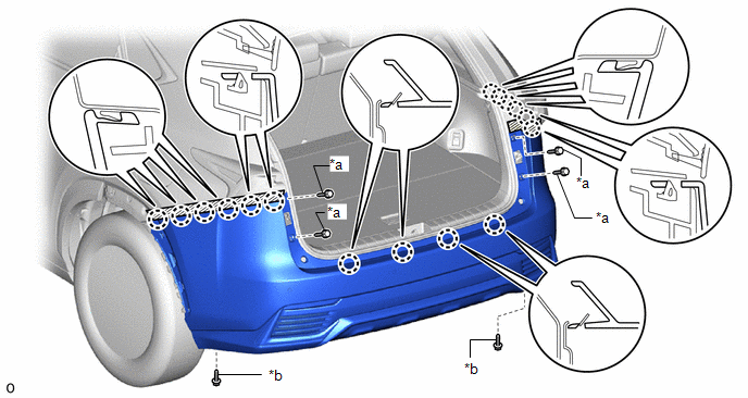
| *a | Screw A | *b | Screw B |
(e) Remove the protective tape.
| (f) Install the clip. HINT: Use the same procedure to install the clip on the other side. |
|
.png)
7. INSTALL REAR BUMPER NO. 1 PLATE
| (a) Attach the 2 claws to install the rear bumper No. 1 plate. HINT: Use the same procedure for all rear bumper No. 1 plates. |
|
.png)
8. INSTALL REAR FLOOR SIDE MEMBER COVER
| (a) Install the rear floor side member cover with the 8 clips. |
|
.png)
9. INSTALL REAR LOWER QUARTER MOULDING PROTECTOR LH
Click here .gif)
10. INSTALL REAR LOWER QUARTER MOULDING PROTECTOR RH
HINT:
Use the same procedure as for the LH side.
11. INSTALL NO. 5 MOULDING TAPE
Click here
12. INSTALL QUARTER OUTSIDE MOULDING SUB-ASSEMBLY LH
Click here
13. INSTALL QUARTER OUTSIDE MOULDING SUB-ASSEMBLY RH
HINT:
Use the same procedure as for the LH side.
14. INSPECT KICK DOOR CONTROL SENSOR (w/ Hands Free Power Back Door)
Click here
15. PERFORM CALIBRATION (w/ Intelligent Clearance Sonar System)
Click here
READ NEXT:
 Components
COMPONENTS ILLUSTRATION *1 DECK FLOOR BOX LH *2 NO. 3 DECK BOARD SUB-ASSEMBLY *3 REAR DECK FLOOR BOX *4 NEGATIVE AUXILIARY BATTERY TERMINAL N*m (kgf*cm, ft.*lbf): Specified
Removal
REMOVAL CAUTION / NOTICE / HINT HINT:
Use the same procedure for the RH and LH sides.
The procedure listed below is for the LH side.
PROCEDURE 1. PRECAUTION NOTICE: After the power switch off
SEE MORE:
Components
COMPONENTS ILLUSTRATION *1 NAVIGATION ANTENNA ASSEMBLY WITH BRACKET *2 NO. 1 HEATER TO REGISTER DUCT SUB-ASSEMBLY *3 UPPER INSTRUMENT PANEL SUB-ASSEMBLY - - ILLUSTRATION *1 ANTENNA CORD SUB-ASSEMBLY *2 NAVIGATION ANTENNA ASSEMBLY *3 NAVIGATION ANTENNA BRACKET
Removal
REMOVAL CAUTION / NOTICE / HINT NOTICE:
Do not replace the spiral with sensor cable sub-assembly with the battery connected and the engine switch on (IG).
Do not rotate the spiral with sensor cable sub-assembly when the following conditions are met: 1) The steering wheel is removed, 2) the batt
