Lexus NX: Removal
REMOVAL
PROCEDURE
1. REMOVE REAR SEAT ASSEMBLY
(a) for Power Seat:
Click here .gif)
(b) for Manual Seat:
Click here
2. REMOVE REAR FLOOR FINISH PLATE
Click here
3. REMOVE REAR DOOR OPENING TRIM WEATHERSTRIP LH
Click here
4. REMOVE UPPER DECK TRIM SIDE BOARD LH
Click here
5. REMOVE ROPE HOOK ASSEMBLY
Click here
6. REMOVE LUGGAGE HOLD BELT STRIKER ASSEMBLY
Click here
7. REMOVE NO. 1 LUGGAGE COMPARTMENT TRIM HOOK
Click here
8. REMOVE DECK TRIM SIDE PANEL ASSEMBLY LH
Click here
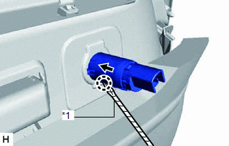
9. REMOVE REAR NO. 1 POWER OUTLET SOCKET ASSEMBLY
| (a) Using a screwdriver, detach the claw to remove the rear No. 1 power outlet socket assembly. HINT:
|
|
10. REMOVE REAR POWER OUTLET SOCKET COVER
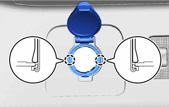
(a) Detach the 2 claws and remove the rear power outlet socket cover.
HINT:
Use the same procedure to remove the other power outlet socket cover.
READ NEXT:
 Installation
INSTALLATION PROCEDURE 1. INSTALL REAR POWER OUTLET SOCKET COVER (a) Attach the 2 claws to install the rear power outlet socket cover. HINT: Use the same procedure to install the other power outlet so
Power Point Socket(for Console Box)
ComponentsCOMPONENTS ILLUSTRATION *1 NO. 1 POWER OUTLET SOCKET ASSEMBLY *2 NO. 1 POWER OUTLET SOCKET COVER *3 NO. 3 BOX PANEL - - RemovalREMOVAL PROCEDURE 1. REMOVE NO. 3 BOX
Relay
On-vehicle InspectionON-VEHICLE INSPECTION PROCEDURE 1. INSPECT POWER OUTLET SOCKET RELAY (a) Remove the power outlet socket relay. (b) Measure the resistance according to the value(s)
SEE MORE:
Hydraulic Control System Malfunction (C1214)
DESCRIPTION The skid control ECU (brake booster with master cylinder assembly) controls braking force according to the hybrid control system regenerative braking force and provides the hydraulic pressure necessary for operating each wheel cylinder according to the wheel cylinder pressure sensor. DTC
Installation
INSTALLATION CAUTION / NOTICE / HINT HINT: A bolt without a torque specification is shown in the standard bolt chart. Click here PROCEDURE 1. INSTALL FRONT BUMPER SIDE RETAINER LH Click here 2. INSTALL FRONT BUMPER SIDE RETAINER RH HINT: Use the same procedure described for the LH side. 3. INSTA
